Friday, July 3, 2015

Fermi Problems and the Annual Background Radiation Dose from Potassium-40

In the very first section of the 5th edition of Intermediate Physics for Medicine and Biology, Russ Hobbie and I emphasize the importance of being able to estimate.
One valuable skill in physics is the ability to make order of magnitude estimates, meaning to calculate something approximately right.
Our first four homework problems at the end of Chapter 1 ask the student to estimate. These exercises are examples of Fermi Problems, after physicist Enrico Fermi who was a master of the skill.

Let us try another of these problems, based on some of the concepts from Chapter 15 about the natural background radiation dose. To be specific, let’s estimate the annual background dose from the radioactive isotope potassium-40 inside our bodies.
Problem 4 ½ Estimate the annual background dose (in mSv/year) from potassium-40 in our bodies. Look up or guess any information you need for this calculation, and clearly explain any assumptions you make.
Begin by considering a single cell. Cells are about 10 microns in size, so their volume is about (10−5 m)3 = 10−15 m3 (the volume we use is not important; it will cancel out in the end). In nerves, the intracellular potassium ion concentration is about 100 mM, but this may overestimate the amount of potassium inside all types of cells. Moreover, the concentration of potassium ions in the extracellular space is much less that in the intracellular space. Let’s guess 50 mM for the average concentration of potassium in our body, meaning 50 millimoles/liter, or 50 moles/m3. If we multiply by Avogadro’s number (6 x 10²³ molecules/mole), we get about 3 x 1025 molecules/m3. So, the number of potassium atoms per cell is 3 x 10¹⁰. This intermediate result is already interesting; there are over ten billion potassium ions in just one cell.

The 40K isotope is radioactive. Its abundance is about 0.01% (abundance data can be found in any table of the isotopes, or even by looking at wikipedia; I don’t know how you could guess that value from first principles). So, this means there are 3 x 10⁶ 40K atoms/cell (a little over a million). How rapidly do these decay? 40K has a half life of 1.25 x 10⁹ years (again, see wikipedia), implying a decay rate of 0.693/1.25 x 109 = 5.5 x 10⁻¹⁰ decays per atom per year. Multiplying by the number of atoms/cell, we get 0.0017 decays per cell per year. This is another interesting result: an average cell has less than a one-percent chance of experiencing a 40K decay in a year. But we have a lot of cells (Russ and I estimate 2 x 10¹⁴ in IPMB), so your body suffers from about 3.4 x 10¹¹ decays per year, or about ten thousand per second. (According to Wikipedia, this estimate is a factor of two too high, but we are not much worried about factors of two in such order-of-magnitude Fermi problems.)

How much energy does each decay deposit in our tissue? Beta decay accounts for 90% of all decays of 40K, and each decay releases an energy of about 1.3 MeV (decay energy data is a little harder to find, but appears in any good table of the isotopes; if you had merely guessed that 1 MeV is the order of magnitude of nuclear decay energies, you would not be too far off). Some of that energy goes to a neutrino, which leaves the body. Let’s assume that on average about 30% of the beta decay energy goes to the electron and that no electrons escape the body, so each decay deposits 0.4 MeV into the cell, or 6 x 10⁻¹⁴ joules. A gray (the unit of dose) is a joule per kilogram, so to calculate dose we need the mass of a cell, which to a first approximation is the product of the density of water (103 kg/m3) times the volume of the cell, or 10−12 kg (I told you the volume of the cell would cancel out). So, the dose is the number of decays per year (0.0017) times the energy per decay (6 x 10⁻¹⁴ J) divided by the mass (10−12 kg), or 0.0001 gray/year. Another unit of dose is the sievert, which accounts for biological damage in addition to energy deposition. A gray and a sievert are the same for electrons, so the annual background dose is 0.0001 Sv, or 0.1 mSv.

In Table 16.6 of IPMB, Russ and I estimate the annual background dose from all internal sources is about 0.3 mSv. Because 40K is not the only isotope in our body that is decaying (for example, carbon-14 is another), we seem to have gotten our order-of-magnitude estimate pretty close. One goal of Chapters 16 and 17 in IPMB is to refine such calculations. For medical purposes you need more accuracy; for a Fermi problem we did okay.

Friday, June 26, 2015

The Electric Potential of a Rectangular Sheet of Charge - Resolved

In the January 9 post of this blog, I challenged readers to find the electrical potential V(z) that will give you the electric field E(z) of Eq. 6.10 in the 5th edition of Intermediate Physics for Medicine and Biology
An expression for the electrical field produced by a rectangular sheet of charge.
In other words, the goal is to find V(z) such that E = − dV/dz produces Eq. 6.10. In the comments at the bottom of the post, a genius named Adam Taylor made a suggestion for V(z) (I love it when people leave comments in this blog). When I tried his expression for the potential, it almost worked, but not quite (of course, there is always a chance I have made a mistake, so check it yourself). But I was able to fix it up with a slight modification. I now present to you, dear reader, the potential:

A complicated expression for the electrical potential of a rectangular sheet of charge.

How do you interpret this ugly beast? The key is the last term, z times the inverse tangent. When you take the z derivative of V(z), you must use the product rule on this term. One derivative in the product rule eliminates the leading z and gives you exactly the inverse tangent you need in the expression for the electric field. The other gives z times a derivative of the inverse tangent, which is complicated. The two terms containing the logarithms are needed to cancel the mess that arises from differentiating tan−1.

I don’t know what there is to gain from having this expression for the potential, but somehow it comforts me to know that if there is an analytic equation for E there is also an analytic equation for V.

Friday, June 19, 2015

Dr. Euler’s Fabulous Formula Cures Many Mathematical Ills

Dr. Euler's Fabulous Formula, by Paul Nahin, superimposed on Intermediate Physics for Medicine and Biology.
Dr. Euler's Fabulous Formula,
by Paul Nahin.
I’ve decided that Leonhard Euler (1707-1783) is my favorite mathematician, and I’m mad at myself for not getting his name mentioned in the 5th edition of Intermediate Physics for Medicine and Biology. I’ve discussed Euler before in this blog, when I reviewed William Dunham’s book Euler: The Master of Us All. I’ve just finished another book, this one by Paul Nahin, about Dr. Euler’s Fabulous Formula. Of course, Nahin means Eq. 11.28 in IPMB,
e = cosθ + i sinθ .

I liked the book, in part because Nahin and I seem to have similar tastes: we both favor the illustrations of Norman Rockwell over the paintings of Jackson Pollock, we both like to quote Winston Churchill, and we both love limericks:
I used to think math was no fun,
‘Cause I couldn’t see how it was done.
    Now Euler’s my hero
    For I now see why zero,
Equals eπi + 1.
Nahin’s book contains a lot of math, and I admit I didn’t go through it all in detail. A large chunk of the text talks about the Fourier series, which Russ Hobbie and I develop in Chapter 11 of IPMB. Nahin motivates the study of the Fourier series as a tool to solve the wave equation. We discuss the wave equation in Chapter 13 of IPMB, but never make the connection between the Fourier series and this equation, perhaps because biomedical applications don’t rely on such an analysis as heavily as, say, predicting how a plucked string vibrates.

Nahin delights in showing how interesting mathematical relationships arise from Fourier analysis. I will provide one example, closely related to a calculation in IPMB. In Section 11.5, we show that the Fourier series of the square wave (y(t) = 1 for t from 0 to T/2 and equal to -1 for t from T/2 to T) is

y(t) = Σ bk cos(k2πt/T)

where the sum is over all odd values of k (k = 1, 3, 5, ....) and bk = 4/(π k). Evaluate both expressions for y(t) at t = T/4. You get

π/4 = 1 – 1/3 + 1/5 – 1/7 +…

This lovely result is hidden in IPMB’s Eq. 11.36. Warning: this is not a particularly useful algorithm for calculating π, as it converges slowly; including ten terms in the sum gives π = 3.04, which is still over 3% off.

In Figure 11.17, Russ and I discuss the Gibbs phenomenon: spikes that occur in y(t) at discontinuities when the Fourier series includes only a finite number of terms. Nahin makes the same point with the periodic function y(t) = (π – t)/2 for t from 0 to 2π. He describes the history of the Gibbs phenomena, which arises from a series of published letters between Josiah Gibbs, Albert Michelson, A. E. H. Love, and Henri Poincare. Interestingly, the Gibbs phenomenon was discovered long before Gibbs by the English mathematician Henry Wilbraham.

Fourier series did not originate with Joseph Fourier. Euler, for example, was known to write such trigonometric series. Fourier transforms (the extension of Fourier series to nonperiodic functions), on the other hand, were first presented by Fourier. Nahin discusses many of the same topics that Russ and I cover, including the Dirac delta function, Parseval’s theorem, convolutions, and the autocorrelation.

Nahin concludes with a section about Euler the man and mathematical physicist. I found an interesting connection to biology and medicine: when hired in 1727 by the Imperial Russian Academy of Sciences, it was as a professor of physiology. Euler spent several months before he left for Russia studying physiology, so he would not be totally ignorant of the subject when he arrived in Saint Petersburg!

I will end with a funny story of my own. I was working at Vanderbilt University just as Nashville was enticing a professional football team to move there. One franchise that was looking to move was the Houston Oilers. Once the deal was done, folks in Nashville began debating what to call their new team. They wanted a name that would respect the team’s history, but would also be fitting for its new home. Nashville has always prided itself as the home of many colleges and universities, so a name out of academia seemed appropriate. Some professors in Vanderbilt’s Department of Mathematics came up with what I thought was the perfect choice: call the team the Nashville Eulers. Alas, the name didn’t catch on, but at least I never again was uncertain about how to pronounce Euler.

Friday, June 12, 2015

Circularly Polarized Excitation Pulses, Spin Lock, and T1ρ

In Chapter 18 of the 5th edition of Intermediate Physics for Medicine and Biology, Russ Hobbie and I discuss magnetic resonance imaging. We describe how spins precess in a magnetic field, Bo = Bo k, at their Larmor frequency ω, and show that this behavior is particularly simple when expressed in a rotating frame of reference. We then examine radio-frequency excitation pulses by adding an oscillating magnetic field. Again, the analysis is simpler in the rotating frame. In our book, we apply the oscillating field in the laboratory frame’s x-direction, B1 = B1 cos(ωt) i. The equations of the magnetization are complicated in the rotating frame (Eqs. 18.22-18.24), but become simpler when we average over time (Eq. 18.25). The time-averaged magnetization rotates about the rotating frame’s x' axis with angular frequency γB1/2, where γ is the spin’s gyromagnetic ratio. This motion is crucial for exciting the spins; it rotates them from their equilibrium position parallel to the static magnetic field Bo into a plane perpendicular to Bo.

When I teach medical physics (PHY 326 here at Oakland University), I go over this derivation in class, but the students still need practice. I have them analyze some related examples as homework. For instance, the oscillating magnetic field can be in the y direction, B1 = B1 cos(ωt) j, or can be shifted in time, B1 = B1 sin(ωt) i. Sometimes I even ask them to analyze what happens when the oscillating magnetic field is in the z direction, B1 = B1 cos(ωt) k, parallel to the static field. This orientation is useless for exciting spins, but is useful as practice.

Yet another way to excite spins is using a circularly polarized magnetic field, B1 = B1 cos(ωt) iB1 sin(ωt) j. The analysis of this case is similar to the one in IPMB, with one twist: you don’t need to average over time! Below is a new homework problem illustrating this.
Problem 13 1/2. Assume you have a static magnetic field in the z direction and an oscillating, circularly polarized magnetic field in the x-y plane, B =Bo k + B1 cos(ωt) iB1 sin(ωt) j.
a) Use Eq. 18.12 to derive the equations for the magnetization M in the laboratory frame of reference (ignore relaxation).
b) Use Eq. 18.18 to transform to the rotating coordinate system and derive equations for M'.
c) Interpret these results physically.
I get the same equations as derived in IPMB (Eq. 18.25) except for a factor of one half; the angular frequency in the rotating frame is ω1 = γ B1. Not having to average over time makes the result easier to visualize. You don’t get a complex motion that—on average—rotates the magnetization. Instead, you get a plain old rotation. You can understand this behavior qualitatively without any math by realizing that in the rotating coordinate system the RF circularly polarized magnetic field is stationary, pointing in the x’ direction. The spins simply precess around the seemingly static B1'= B1 i', just like the spins precess around the static Bo = Bo k in the laboratory frame.

Now let’s assume that an RF excitation pulse rotates the magnetization so it aligns with the x' rotating axis. Once the pulse ends, what happens? Well, nothing happens unless we account for relaxation. Without relaxation the magnetization precesses around the static field, which means it just sits there stationary in the rotating frame. But we know that relaxation occurs. Consider the mechanism of dephasing, which underlies the T2* relaxation time constant. Slight heterogeneities in Bo mean that different spins precess at different Larmor frequencies, causing the spins to lose phase coherence, decreasing the net magnetization.

Next, consider the case of spin lock. Imagine an RF pulse rotates the magnetization so it is parallel to the x' rotating axis. Then, when the excitation pulse is over, immediately apply a circularly polarized RF pulse at the Larmor frequency, called B2, which is aligned along the x' rotating axis. In the rotating frame the magnetization is parallel to B2, so nothing happens. Why bother? Consider those slight heterogeneities in Bo that led to T2* relaxation. They will cause the spins to dephase, picking up a component in the y' direction. But a component along y' will start to precess around B2. Rather than dephasing, B2 causes the spins to wobble around in the rotating frame, precessing about x', with no net tendency to dephase. You just killed the mechanism leading to T2*! Wow!

Will the spins just precess about B2 forever? No, eventually other mechanisms will cause them to relax toward their equilibrium value. Their time constant will not be T1 or T2 or even T2*, but something else called T. Typcially, T is much longer than T2*. To measure T, apply a 90 degree excitation pulse, then apply a RF spin lock oscillation and record the free induction decay. Fit the decay to an exponential, and the time constant you obtain is T. (I am not a MRI expert: I am not sure how you can measure a free induction decay when a spin lock field is present. I would think the spin lock field would swamp the FID.)

T is sometimes measured to learn about the structure of cartilage. It is analogous to T1 relaxation in the laboratory frame, which explains its name. Because B2 is typically much weaker than Bo, T is sensitive to a different range of correlation times than T1 or T2 (see Fig. 18.12 in IPMB).

Friday, June 5, 2015

Robert Plonsey (1924-2015)

Bioelectricity: A Quantitative Approach, by Plonsey and Barr, superimposed on Intermediate Physics for Medicine and Biology.
Bioelectricity: A Quantitative Approach,
by Plonsey and Barr.
The eminent biomedical engineer Robert Plonsey died on March 14. Readers of the 5th edition of Intermediate Physics for Medicine and Biology will be familiar with Plonsey, as Russ Hobbie and I cite nine of his publications. I read Plonsey’s classic textbook Bioelectric Phenomena (1969) in graduate school, and I have taught from his book Bioelectricity: A Quantitative Approach with Roger Barr. I discussed previously in this blog his book Bioelectromagnetism with Jaakko Malmivuo.

Plonsey had an enormous impact on my research when I was in graduate school. For example, in 1968 John Clark and Plonsey calculated the intracellular and extracellular potentials produced by a propagating action potential along a nerve axon (“The Extracellular Potential Field of a Single Active Nerve Fiber in a Volume Conductor,” Biophysical Journal, Volume 8, Pages 842−864). Russ and I outline this calculation--which uses Bessel functions and Fourier transforms--in IPMB’s Homework Problem 30 of Chapter 6. In one of my first papers, Jim Woosley, my PhD advisor John Wikswo, and I extended Clark and Plonsey’s calculation to predict the axon’s magnetic field (Woosley, Roth, and Wikswo, 1985, “The Magnetic Field of a Single Axon: A Volume Conductor Model,” Mathematical Bioscience, Volume 76, Pages 1−36). I have described Clark and Plonsey’s groundbreaking work before in this blog.

I associate Plonsey most closely with the development of the bidomain model of cardiac tissue. The 1980s was an exciting time to be doing cardiac electrophysiology, and Duke University, where Plonsey worked, was the hub of this activity. Wikswo, Nestor Sepulveda, and I, all at Vanderbilt University, had to run fast to compete with the Duke juggernaut that included Plonsey, Barr, Ray Ideker, Theo Pilkington, and Madison Spach, as well as a triumvirate of then up-and-coming researchers from my generation: Natalia Trayanova, Wanda Krassowska, and Craig Henriquez. To get a glimpse of these times (to me, the “good old days”), read Henriquez’s “A Brief History of Tissue Models for Cardiac Electrophysiology” (IEEE Transaction on Biomedical Engineering, Volume 61, Pages 1457−1465) published last year.

My first work on the bidomain model was to extend Clark and Plonsey’s calculation of the potential along a nerve axon to an analogous calculation along a cylindrical strand of cardiac tissue, such as a papillary muscle (Roth and Wikswo, 1986, “A Bidomain Model for Extracellular Potential and Magnetic Field of Cardiac Tissue,” IEEE Transaction on Biomedical Engineering, Volume 33, Pages 467−469). I remember what an honor it was for me when Plonsey and Barr cited our paper (and mentioned John and me by name!) in their 1987 article “Interstitial Potentials and Their Change with Depth into Cardiac Tissue” (Biophysical Journal, Volume 51, Pages 547−555). That was heady stuff for a nobody graduate student who could count his citations on his ten fingers.

One day Wikswo returned from a conference and told us about a talk he heard, by either Plonsey or Barr (I don’t recall which), describing the action current distribution produced by a outwardly propagating wave front in a sheet of cardiac tissue (Plonsey and Barr, 1984, “Current Flow Patterns in Two-Dimensional Anisotropic Bisyncytia with Normal and Extreme Conductivities,” Biophysical Journal, Volume 45, Pages 557−571). Wikswo realized immediately that their calculations implied the wave front would have a distinctive magnetic signature, which he and Nestor Sepulveda reported in 1987 (“Electric and Magnetic Fields From Two-Dimensional Anisotropic Bisyncytia,” Biophysical Journal, Volume 51, Pages 557−568).

In another paper, Barr and Plonsey derived a numerical method to solve the bidomain equations including the nonlinear ion channel kinetics (Barr and Plonsey, 1984, “Propagation of Excitation in Idealized Anisotropic Two-Dimensional Tissue,” Biophysical Journal, Volume 45, Pages 1191−1202). This paper was the inspiration for my own numerical algorithm (Roth, 1991, “Action Potential Propagation in a Thick Strand of Cardiac Muscle,” Circulation Research, Volume 68, Pages 162−173). In my paper, I cited several of Plonsey’s articles, including one by Plonsey, Henriquez, and Trayanova about an “Extracellular (Volume Conductor) Effect on Adjoining Cardiac Muscle Electrophysiology” (1988, Medical and Biological Engineering and Computing, Volume 26, Pages 126−129), which shared the conclusion I reached that an adjacent bath can dramatically affect action potential propagation in cardiac tissue. Indeed, Henriquez (Plonsey’s graduate student) and Plonsey were following a similar line of research, resulting in two papers partially anticipating mine (Henriquez and Plonsey, 1990, “Simulation of Propagation Along a Cylindrical Bundle of Cardiac Tissue—I: Mathematical Formulation,” IEEE Transactions on Biomedical Engineering, Volume 37, Pages 850−860; and Henriquez and Plonsey, 1990, “Simulation of Propagation Along a Cylindrical Bundle of Cardiac Tissue—II: Results of Simulation,” IEEE Transactions on Biomedical Engineering, Volume 37, Pages 861−875.)

In parallel with this research, Ideker was analyzing how defibrillation shocks affected cardiac tissue, and in 1986 Plonsey and Barr published two papers presenting their saw tooth model (“Effect of Microscopic and Macroscopic Discontinuities on the Response of Cardiac Tissue to Defibrillating (Stimulating) Currents,” Medical and Biological Engineering and Computing, Volume 24, Pages 130−136; “Inclusion of Junction Elements in a Linear Cardiac Model Through Secondary Sources: Application to Defibrillation,” Volume 24, Pages 127−144). (It’s interesting how many of Plonsey’s papers were published as pairs.) I suspect that if in 1989 Sepulveda, Wikswo and I had not published our article about unipolar stimulation of cardiac tissue (“Current Injection into a Two-Dimensional Anisotropic Bidomain,” Biophysical Journal, Volume 55, Pages 987−999), one of the Duke researchers—perhaps Plonsey himself—would have soon performed the calculation. (To learn more about the Sepulveda et al paper, read my May 2009 blog entry.)

In January 1991 I visited Duke and gave a talk in the Emerging Cardiovascular Technologies Seminar Series, where I had the good fortune to meet with Plonsey. Somewhere I have a videotape of that talk; I suppose I should get it converted to a digital format. When I was working at the National Institutes of Health in the mid 1990s, Plonsey was a member of an external committee that assessed my work, as a sort of tenure review. I will always be grateful for the positive feedback I received, although it was to no avail because budget cuts and a hiring freeze led to my leaving NIH in 1995. Plonsey retired from Duke in 1996, and our paths didn’t cross again. He was a gracious gentleman who I will always have enormous respect for. Indeed, the first seven years of my professional life were spent traveling down a path parallel to and often intersecting his; to put it more aptly, I was dashing down a trail he had blazed.

Robert Plonsey was a World War Two veteran (we are losing them too fast these days), and a leader in establishing biomedical engineering as an academic discipline. You can read his obituary here and here.

I will miss him.

Friday, May 29, 2015

Taylor's Series

In Appendix D of the 5th edition of Intermediate Physics for Medicine and Biology, Russ Hobbie and I review Taylor’s Series. Our Figures D.3 and D.4 show better and better approximations to the exponential function, ex, found by using more and more terms of its Taylor’s series. As we add terms, the approximation improves for small |x| and diverges more slowly for large |x|. Taking additional terms from the Taylor’s series approximates the exponential by higher and higher order polynomials. This is all interesting and useful, but the exponential looks similar to a polynomial, at least for positive x, so it is not too surprising that polynomials do a decent job approximating the exponential.

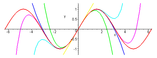
A more challenging function to fit with a Taylor’s Series would look nothing like a polynomial, which always grows to plus or minus infinity at large |x|. I wonder how the Taylor’s Series does approximating a bounded function; perhaps a function that oscillates back and forth a lot? The natural choice is the sine function.

The Taylor’s Series of sin(x) is

sin(x) = xx3/6 + x5/120 – x7/5040 + x9/362880 - …

The figure below shows the sine function and its various polynomial approximations.

The sine function at various polynomial approximations, derived from its Taylor's series.
The sine function and its various polynomial approximations,
from: http://www.peterstone.name/Maplepgs/images/Maclaurin_sine.gif
The red curve is the sine function itself. The simplest approximation is simply sin(x) = x, which gives the yellow straight line. It looks good for |x| less than one, but quickly diverges from sine at large |x|. The green curve is sin(x) = xx3/6. It rises to a maximum and then falls, much like sin(x), but  heads off to plus or minus infinity relatively quickly. The cyan curve is sin(x) = x – x3/6 + x5/120. It captures the first peak of the oscillation well, but then fails. The royal blue curve is sin(x) = xx3/6 + x5/120 – x7/5040. It is an excellent approximation of sin(x) out to x = π. The violet curve is sin(x) = xx3/6 + x5/120 – x7/5040 + x9/362880. It begins to capture the second oscillation, but then diverges. You can see the Taylor’s Series is working hard to represent the sine function, but it is not easy.

Appendix D in IPMB gives a table of values of the exponential and its different Taylor’s Series approximations. Below I create a similar table for the sine. Because the sine and all its series approximations are odd functions, I only consider positive values of x.

A table of values for sin(x) and its various polynomial approximations.

One final thought. Russ and I title Appendix D as “Taylor’s Series” with an apostrophe s. Should we write “Taylor Series” instead, without the apostrophe s? Wikipedia just calls it the “Taylor Series.” I’ve seen it both ways, and I don’t know which is correct. Any opinions?

Friday, May 22, 2015

Progress Toward a Deployable SQUID-Based Ultra-Low Field MRI System for Anatomical Imaging

When surfing the web, I like to visit medicalphysicsweb.org. This site, maintained by the Institute of Physics, always publishes interesting and up-to-date information about physics applied to medicine. Readers of the 5th Edition of Intermediate Physics for Medicine and Biology should visit it regularly.

A recent article discusses a paper by Michelle Espy and her colleagues about “Progress Toward a Deployable SQUID-Based Ultra-Low Field MRI System for Anatomical Imaging” (IEEE Transactions on Applied Superconductivity, Volume 25, Article Number 1601705, June 2015). The abstract is given below.
Magnetic resonance imaging (MRI) is the best method for non-invasive imaging of soft tissue anatomy, saving countless lives each year. But conventional MRI relies on very high fixed strength magnetic fields, ≥ 1.5 T, with parts-per-million homogeneity, requiring large and expensive magnets. This is because in conventional Faraday-coil based systems the signal scales approximately with the square of the magnetic field. Recent demonstrations have shown that MRI can be performed at much lower magnetic fields (∼100 μT, the ULF regime). Through the use of pulsed prepolarization at magnetic fields from ∼10–100 mT and SQUID detection during readout (proton Larmor frequencies on the order of a few kHz), some of the signal loss can be mitigated. Our group and others have shown promising applications of ULF MRI of human anatomy including the brain, enhanced contrast between tissues, and imaging in the presence of (and even through) metal. Although much of the required core technology has been demonstrated, ULF MRI systems still suffer from long imaging times, relatively poor quality images, and remain confined to the R and D laboratory due to the strict requirements for a low noise environment isolated from almost all ambient electromagnetic fields. Our goal in the work presented here is to move ULF MRI from a proof-of-concept in our laboratory to a functional prototype that will exploit the inherent advantages of the approach, and enable increased accessibility. Here we present results from a seven-channel SQUID-based system that achieves pre-polarization field of 100 mT over a 200 cm3 volume, is powered with all magnetic field generation from standard MRI amplifier technology, and uses off the shelf data acquisition. As our ultimate aim is unshielded operation, we also demonstrated a seven-channel system that performs ULF MRI outside of heavy magnetically-shielded enclosure. In this paper we present preliminary images and compare them to a model, and characterize the present and expected performance of this system.
Let’s compare a standard 1.5-Tesla clinical MRI system with Espy et al.’s ultra-low field device. To compare quantities using the same units, I will always express the magnetic field strength in mT; a typical clinical MRI machine has a field of 1500 mT. In Section 18.3 of IPMB, Russ Hobbie and I show that the magnetization depends linearly on the magnetic field strength (Equation 18.9). The static magnetic field of Espy et al.’s machine is 0.2 mT, but for 4000 ms before spin excitation a polarization magnetic field of 100 mT is turned on. Thus, there is a difference of a factor of 15 in the magnetization, with the ultra-low device having less and the clinical machine more. Once the polarization field is turned off, the magnetic field in the ultra-low device reduces to 0.2 mT. This is only four times the earth’s magnetic field, about 0.05 mT. Espy et al. use Hemlholtz coils to cancel the earth’s field.

A magnetic field of 1500 mT is usually produced by a coil that must be kept at low temperatures to maintain the wire as a superconductor. A 100 mT field does not require superconductivity, but the needed current generates enough heat that the 510-turn copper coil needs to be cooled by liquid nitrogen, and even still the current in the coil must be turned off half the time (50% duty cycle) to avoid overheating.

Once the polarization field turns off, the spins precess with the Larmor frequency for a 0.2 mT magnetic field. The gyromagnetic ratio of protons is 42.6 kHz/mT, implying a Larmor frequency of 8.5 kHz, compared with 64,000 kHz for a clinical machine. So, the Larmor frequencies differ by a factor of 7500.

The magnetic resonance signal recorded in a clinical system is large compared to an ultra-low device because the magnetization is larger by a factor of 15 and the Larmor frequency is larger by a factor of 7500, implying a signal over a hundred thousand times larger. Espy et al. get around this problem by measuring the signal with a Superconducting Quantum Interference Device (SQUID) magnetometer, like those used in magnetoencephalography (see Section 8.9 in IPMB).

Preliminary experiments were performed in a heavy and expensive magnetically shielded room (again, like those used when measuring the MEG). However, second-order gradiometer pickup coils reduce the noise sufficiently that the shielded room is unnecessary.

To perform imaging, Espy et al. use magnetic field gradients of about 0.00025 mT/mm, compared with 0.01 mT/mm gradients typical for clinical MRI. For two objects 1 mm apart, a clinical imaging system would therefore produce a fractional frequency shift of 0.01/1500 = 0.0000067 or 6.7 ppm, whereas a low-field device has a fractional shift of 0.00025/0.2 = 0.00125 or 1250 ppm. Therefore, the clinical magnetic field needs to be extremely homogeneous (on the order of parts per million) to avoid artifacts, whereas a low-field device can function with heterogeneities hundreds of times larger.

The relaxation time constants for gray matter in the brain are reported by Espy et al. as about T1 = 600 ms and T2 = 80 ms. In clinical devices, the value of T1 is about half that, and T2 is about the same. Based on Figure 18.12 and Equation 18.35 in IPMB, I’m not surprised that T2 is largely independent of the magnetic field strength. However, in strong fields T1 increases as the square of the magnetic field (or the square of the Larmor frequency), so I was initially expecting a much smaller value of T1 for the low-field device. But once the Larmor frequency drops to values less than the typical correlation time of the spins, T1 becomes independent of the magnetic field strength (Equation 18.34 in IPMB). I assume that is what is happening here, and explains why T1 drops by only a factor of two when the magnetic field is reduced by a factor of 7500.

I find the differences between radio-frequency excitation pulses to be interesting. In clinical imaging, if the excitation pulse has a duration of about 1 ms and the Larmor frequency is 64,000 kHz, there are 64,000 oscillations of the radio-frequency magnetic field in a single π/2 pulse. Espy et al. used a 4 ms duration excitation pulse and a Larmor frequency of 8.5 kHz, implying just 34 oscillations per pulse. I have always worried that illustrations such as Figure 18.23 in IPMB mislead because they show the Larmor frequency as being not too different from the excitation pulse duration. For low-field MRI, however, this picture is realistic.

Does low-field MRI have advantages? You don’t need the heavy, expensive superconducting coil to generate a large static field, but you do need SQUID magnetometers to record the small signal, so you don’t avoid the need for cryogenics. The medicalphysicsweb article weighs the pros and cons. For instance, the power requirements for a low-field device are relatively small, and it is more portable, but the imaging times are long. The safety hazards caused by metal are much less in a low-field system, but the impact of stray magnetic fields is greater. I’m skeptical about the ultimate usefulness of ultra low-field MRI, but it’ll be fun to watch if Espy and her team can prove me wrong.

Friday, May 15, 2015

What My Dogs Forced Me To Learn About Thermal Energy Transfer

I’m a dog lover, so I have to enjoy an American Journal of Physics paper that begins “For many years, I have competed and judged in American Kennel Club obedience trials.” The title of the paper is also delightful: “What my Dogs Forced Me to Learn About Thermal Energy Transfer” (Craig Bohren, American Journal of Physics, Volume 83, Pages 443−446, 2015). Bohren’s hypothesis is that an animal perceives hotness and coldness not directly from an object’s temperature, as one might naively expect, but from the flux density of thermal energy. I could follow his analysis of this idea, but I prefer to use the 5th edition of Intermediate Physics for Medicine and Biology, because Russ Hobbie and I have already worked out almost all the results we need.

Chapter 4 of IPMB analyzes diffusion. We consider the concentration, C, of particles as they diffuse in one dimension. Initially (t = 0), there exists a concentration difference C0 between the left and right sides of a boundary at x = 0. We solve the diffusion equation in this case, and find the concentration in terms of an error function

  C(x,t) = C0/2 [ 1 – erf(x/√4Dt) ] ,                  Eq. 4.75

where D is the diffusion constant. A plot of C(x,t) is shown in Fig. 4.22 (we assume C = 0 on the far right, but you could add a constant to the solution without changing the physics, so all that really matters is the concentration difference).

Fig. 4.22 from Intermediate Physics for Medicine and Biology, showing the spread of an initially sharp boundary due to diffusion.
Fig. 4.22 The spread of an initially sharp boundary due to diffusion.
In Homework Problem 19, Russ and I show that the analysis of particle diffusion is equivalent to an analysis of heat conduction, with the thermal diffusivity D given by the thermal conductivity, κ, divided by the specific heat capacity, c, and the density, ρ

D = κ/cρ .

So, by analogy, if you start (t = 0) with a uniform temperature on the left and on the right sides of a boundary at x = 0, with an initial temperature difference ΔT between sides, the temperature distribution T(x,t) is (to within a additive constant temperature) the same as the concentration distribution calculated earlier.

T(x,t) = ΔT /2 [ 1 – erf(x/√4Dt) ] .

The temperature of the interface is always ΔT/2. If a dog responded to simply the temperature at x = 0 (where its thermoreceptors are presumably located), it would react in a way strictly proportional to the temperature difference ΔT. But Bohren’s hypothesis is that thermoreceptors respond to the energy flux density, κ dT/dx.

Now let us look again at Fig. 4.22. The slope of the curve at x = 0 is the key quantity. So, we must differentiate our expression for T(x,t). We get

κ dT/dx = - κ ΔT/2 d/dx [ erf(x/√4Dt) ] .

By the chain rule, this becomes (with u = x/√4Dt)

κ dT/dx  = - κ ΔT / (2 √4Dt ) d(erf(u))/du .

The derivative of the error function is given in IPMB on page 179

d/du (erf(u)) = 2/√π e-u2 .

At the interface (u = 0), this becomes 2/√π. Therefore

κ dT/dx = - κ ΔT /√4πDt .

Bohren comes to the same result, but by a slightly different argument.

The energy flux density depends on time, with an infinite response initially (we assume an abrupt difference of temperature on the two sides of the boundary x = 0) that falls to zero as the time becomes large. The flux density depends on the material parameters by the quantity κ/√D , which is equivalent to √cρκ and is often called the thermal inertia.

Bohren goes on to analyze the case when the two sides have different properties (for example, the left might be a piece of aluminum, and the right a dog’s tongue), and shows that you get a similar result except the effective thermal inertia is a combination of the thermal inertia on the left and right. He does not solve the entire bioheat equation (Sec. 14.11 in IPMB), including the effect of blood flow. I would guess that blood flow would have little effect initially, but it would play a greater and greater role as time goes by.

Perhaps I will try Bohren’s experiment: I’ll give Auggie (my daughter Kathy’s lovable foxhound) a cylinder of aluminum and a cylinder of stainless steel, and see if he can distinguish between the two. My prediction is that, rather than either metal, he prefers rawhide.

Friday, May 8, 2015

The blog is dead. Long live the blog!

Intermediate Physics for Medicine and Biology.
Intermediate Physics for
Medicine and Biology.
All good things must come to an end. After nearly eight years of posting an entry to this blog every Friday morning, I must say goodbye. This is the last entry to my blog dedicated to the 4th edition of Intermediate Physics for Medicine and Biology. I hope you have found it useful.

Next week will be the first entry to the blog for the FIFTH edition of Intermediate Physics for Medicine and Biology! You can now purchase the 5th edition at the Springer website. Amazon does not have a page for the book yet, but it should be coming soon.

What’s new in the 5th edition? The preface states
The Fifth Edition does not add any new chapters, but almost every page has been improved and updated. Again, we fought the temptation to expand the book and deleted material when possible. Some of the deleted material is available at the book’s website: [https://sites.google.com/view/hobbieroth]. The Fifth Edition has 12% more end-of-chapter problems than the Fourth Edition; most highlight biological applications of the physical principles. Many of the problems extend the material in the text. A solutions manual is available to those teaching the course. Instructors can use it as a reference or provide selected solutions to their students. The solutions manual makes it much easier for an instructor to guide an independent-study student. Information about the solutions manual is available at the book’s website.
The 5th edition is only 13 pages longer than the 4th. By deleting or condensing obsolete or less important topics, we made room for some new sections, including
  • 1.2 Models (about toy models and their different roles in biology and physics)
  • 1.15 Diving (SCUBA diving and the bends)
  • 2.6 The Chemostat
  • 8.1.2 The Cyclotron
  • 8.8.4 Magnetic nanoparticles
  • 9.10.5 Microwaves, Mobile Phones, and Wi-Fi
  • 10.7 Proportional, Derivative, and Integral Control
  • 13.1.3 Shear waves
  • 13.7.4 Elastography (using ultrasound imaging)
  • 13.7.5 Safety (of ultrasound imaging)
  • 14.2 Electron Waves and Particles: The Electron Microscope
  • 14.9.2 Photodynamic Therapy
  • 14.15 Color Vision
  • 18.14 Hyperpolarized MRI of the Lung
There is no errata yet, but despite our best efforts to find and remove all mistakes I suspect we will start finding errors in the 5th edition soon, and we’ll tell you about them if we do. As always, if YOU find errors in the book, please let us know.

Enjoy!

Friday, May 1, 2015

Churchill’s moral

The Second World War,  by WInston Churchill, with Intermediate Physics for Medicine and Biology.
The Second World War,
by Winston Churchill.
Winston Churchill is one of my heroes. After completing my PhD dissertation, I rewarded myself by reading Churchill’s history The Second World War; all six volumes. I am amazed how someone could make so much history leading England through World War Two, and then write that history so well. I love his language, and the way he uses his memos and letters to illustrate his thoughts at the time the events happened, rather than relying on his memories of those events years later. His life story is fascinating, and is told eloquently by the late William Manchester in his biography of Churchill, The Last Lion.

One unique feature of Churchill’s history is that he gave it a moral:

Moral of the Work

In War: Resolution
In Defeat: Defiance
In Victory: Magnanimity
In Peace: Goodwill

All books should have a moral, which sums up its key message in just a handful of carefully chosen words, and highlights the crucial lessons readers should learn. A moral is not an abstract, meant to summarize the book. Rather than explaining what the book is about, a moral tells why you should bother reading the book at all.

What would be the moral of the 4th edition of Intermediate Physics for Medicine and Biology? I cannot capture the essence of IPMB as well as Churchill did his history, but I must try. The moral of IPMB should express how physics explains and constrains biology and medicine, how you cannot truly understand biology until you can describe it in the language of mathematics, how so much of what is learned in introductory physics has direct applications to modern medicine, how toy models provide a way to reduce complex biological processes to their fundamental mechanisms, how the goal of expressing phenomena in mathematics is not merely to calculate numbers but to tell a physical story, and how solving homework problems is the most important way (more important that reading the book!) to learn crucial modeling skills. So, with apologies to Sir Winston, I present the moral of Intermediate Physics for Medicine and Biology:

Moral of the Work

 In Physics: Physiology
In Math: Medicine
In Models: Comprehension
In Equations: Insight

Friday, April 24, 2015

Figure 13.5

In Chapter 13 of the 4th edition of Intermediate Physics for Medicine and Biology, Russ Hobbie and I discuss imaging using ultrasound. One of the key concepts in this chapter is the reflection of an ultrasonic wave at the boundary between tissues having different acoustic impedances. The acoustic impedance is equal to the square root of ρ/κ, where ρ is the density and κ is the compressibility. An ultrasonic image is formed by recording echoes of an ultrasonic wave and using the timing of those echoes to determine the distance from tissue boundaries.

Figure 13.5 from Intermediate Physics for Medicine and Biology.
Figure 13.5 shows schematically how part of a pressure wave approaching a surface (the incident wave) passes through the surface (the transmitted wave) and part travels back toward the wave’s source (the reflected wave, or echo). When you look closely, however, there is something odd about this figure: the transmitted wave has a larger amplitude than the incident wave. How can this be? Doesn’t this violate some conservation law? If we consider particles rather than waves, we would expect that if 100 particles were incident on a surface, perhaps 75 of them would be transmitted and 25 reflected. Figure 13.5 seems to imply that 100 incident particles result in 133 transmitted and 33 reflected! How?

The figure is not wrong; the problem is with our intuition. Pressure is not a conserved quantity. There is no reason to expect the sum of the pressures of the transmitted and reflected waves to equal the pressure of the incident wave. The amplitudes are consistent with equations 13.26 and 13.27 in IPMB relating the three waves. Yet there is a conserved quantity, one we all know: energy.

The intensity of a wave is the energy per unit area per unit time. The intensity I, pressure p, and acoustic impedance Z are related by equation 13.29: I = p2/2Z. The transmitted wave in Fig. 13.5 has a pressure amplitude that is 1.33 times the amplitude of the incident wave, but it is moving through a tissue that has twice the acoustic impedance (the caption says that for this figure, Z2 = 2 Z1). For simplicity, take the acoustic impedance on the left (the incident side of the boundary, region 1) to be Z1 = 0.5 and the amplitude of the incident wave to be pi = 1 (let’s not worry about units for now, because our goal is to compare the relative intensities of the three waves). In this case, the intensity of the incident wave is equal to one. If the transmitted pressure is 1.33 and the acoustic impedance on the right (region 2) is Z2 = 1 (twice Z1), then the transmitted intensity is (1.33)2/2 = 0.89. The reflected wave has amplitude 0.33, and is propagating through the tissue on the left, so its intensity is (0.33)2/1 = 0.11. The sum of the intensities of the transmitted and reflected waves, 0.89 + 0.11, is equal to the intensity of the incident wave. Energy is conserved! The figure is correct after all.

Here is another way to think about intensity: it’s one half of the product of the pressure times the tissue speed. When I say “tissue speed” I don’t mean the propagation speed of the wave, but the speed of the tissue itself as it oscillates back and forth. The acoustic impedance relates the pressure and tissue speed. The large pressure of the transmitted wave is associated with a small tissue speed. The transmitted wave in Fig. 13.5 looks “big” only because we plot the pressure. Had we plotted tissue speed instead, we would not be wondering why the transmitted wave has such a large amplitude. We would, however, be scratching our head about a funny phase shift in the reflected wave, which the version of the figure showing the pressure hides.

So, Fig. 13.5 is correct. Does that mean it looks exactly the same in the 5th edition of IPMB (due out this summer)? No, we did change the figure; not to correct an error, but to emphasize another point. Figure 13.5, as presently drawn, shows the wavelength of the transmitted wave to be the same as the wavelength of the incident wave. The wavelength does not depend on the acoustic impedance, but it does depend on the wave speed (the propagation speed of the wave itself, usually given the symbol c, which is not the same as the speed of the oscillating tissue). The wave speed is equal to the square root of the reciprocal of the product of the density and compressibility. One can cook up examples where two tissues have the same wave speed but different acoustic impedances. For instance (again, not worrying about units and only comparing relative sizes), if the tissue on the left had twice the compressibility and half the density of the tissue on the right, then the left would have half the acoustic impedance and the same wave speed as the right, just as shown in Fig. 13.5. But tissues usually differ in compressibility by a greater factor than they differ in density. If we assume the two regions have the same density but the right has one-fourth the compressibility, then Z2 = 2 Z1 as before but also c2 = 2 c1, so the wavelength is longer on the right. In the 5th edition, the figure now shows the wavelength longer on the right.

What is the moral to this story? Readers (and authors) need to think carefully about illustrations such as Fig. 13.5. They tell a physical story that is often richer and more complicated than we may initially realize.

Friday, April 17, 2015

Physical Models of Living Systems

Physical Models of Living Systems, by Philip Nelson, superimposed on Intermediate Physics for Medicine and Biology.
Physical Models of
Living Systems,
by Philip Nelson.
Philip Nelson has a new textbook that came out earlier this year: Physical Models of Living Systems. It’s an excellent book, well written and beautifully illustrated. The target audience is similar to that for the 4th edition of Intermediate Physics for Medicine and Biology: upper-level undergraduates who have studied physics and math at the introductory level. Like IPMB, it stresses the construction of physical and mathematical models of living systems.

At the start of the book, Nelson provides a section labeled “To the Student.” I hope students read this, as it provides much wisdom and advice. In fact, most of this advice applies as well to IPMB. I found his discussion of “skills” to be so valuable that I reproduce it here.
Science is not just a pile of facts for you to memorize. Certainly you need to know many facts, and this book will supply some as background to the case studies. But you also need skills. Skills cannot be gained just by reading through this (or any) book. Instead you’ll need to work through at least some of the exercises, both those at the ends of chapters and others sprinkled throughout the text.

Specifically, this book emphasizes

Model construction skills: It's important to find an appropriate level of description and then write formulas that make sense at that level. (Is randomness likely to be an essential feature of this system? Does the proposed model check out at the level of dimensional analysis?) When reading others’ work, too, it’s important to be able to grasp what assumptions their model embodies, what approximations are being made, and so on.

Interconnection skills: Physical models can bridge topics that are not normally discussed together, by uncovering a hidden similarity. Many big advances in science came about when someone found an analogy of this sort.

Critical skills: Sometimes a beloved physical model turns out to be . . . wrong. Aristotle taught that the main function of the brain was to cool the blood. To evaluate more modern hypotheses, you generally need to understand how raw data can give us information, and then understanding.

Computer skills: Especially when studying biological systems, it’s usually necessary to run many trials, each of which will give slightly different results. The experimental data very quickly outstrip our abilities to handle them by using the analytical tools taught in math classes. Not very long ago, a book like this one would have to content itself with telling you things that faraway people had done; you couldn’t do the actual analysis yourself, because it was too difficult to make computers do anything. Today you can do industrial-strength analysis on any personal computer.

Communication skills: The biggest discovery is of little use until it makes it all the way into another person’s brain. For this to happen reliably, you need to sharpen some communication skills. So when writing up your answers to the problems in this book, imagine that you are preparing a report for peer review by a skeptical reader. Can you take another few minutes to make it easier to figure out what you did and why? Can you label graph axes better, add comments to your code for readability, or justify a step? Can you anticipate objections?

You'll need skills like these for reading primary research literature, for interpreting your own data when you do experiments, and even for evaluating the many statistical and pseudostatistical claims you read in the newspapers.

One more skill deserves separate mention. Some of the book’s problems may sound suspiciously vague, for example, “Comment on . . .” They are intentionally written to make you ask, “What is interesting and worthy of comment here?” There are multiple “right” answers, because there may be more than one interesting thing to say. In your own scientific research, nobody will tell you the questions. So it’s good to get the habit of asking yourself such things.
Nelson begins the book by discussing virus dynamics, and specifically analyzes the work of Alan Perelson, who constructs mathematical model of how the human immunodeficinecy virus interacts with our immune system. Here at Oakland University, Libin Rong (a former postdoc of Perelson’s) does similar research, and their work is an excellent case study in using mathematics to model a biological process.

A large fraction of the book examines the role of randomness in biology, leading to a detailed analysis of probability. Nelson provides an elegant discussion of the experiments of Max Delbruck and Salvador Luria.
S. Luria and M. Delbruck set out to explore inheritance in bacteria in 1943. Besides addressing a basic biological problem, this work developed a key mode of scientific thought. The authors laid out two competing hypotheses, and sought to generate testable quantitative predictions from them. But unusually for the time, the predictions were probabilistic in character. No conclusion can be drawn from any single bacterium—sometimes it gains resistance; usually it doesn’t. But the pattern of large numbers of bacteria has bearing on mechanism. We will see how randomness, often dismissed as an unwelcome inadequacy of an experiment, turned out to be the most interesting feature of the data.
Perhaps one way to appreciate the differences between Physical Models of Living Systems and IPMB is to compare how each handles diffusion. Russ Hobbie and I consider diffusion in Chapter 4 of IPMB; we describe diffusion as arising from a concentration gradient (Fick’s first law), and use the continuity equation to derive the diffusion equation (Fick’s second law). These relationships are macroscopic descriptions of diffusion. Then, at the end of the chapter—almost as an afterthought—we show that diffusion can be thought of as a random walk. Nelson, on the other hand, starts by analyzing the random nature of diffusion using probabilistic ideas, and then—almost as an afterthought—derives the diffusion equation (or at least a discrete approximation of it). I think this example reflects the different approaches of the two books: IPMB generally takes a macroscopic approach but sometimes reaches down with an example at the microscopic level, whereas Physical Models in Living Systems typically starts with a microscopic description and then sometimes works its way up to the macroscopic level.

Both books also have an extensive analysis of feedback. The canonical example in IPMB comes from physiology at the organism level: breathing rate controls and is controlled by blood carbon dioxide concentration. In Physical Models in Living Systems, a central example is how bacteria use feedback to regulate the synthesis of the amino acid tryptophan. Both case studies are excellent examples of negative feedback, but at different spatial scales. One example is not better than the other; they’re merely different illustrations of the same idea.

One strength of Physical Models of Living Systems is its emphasis on using computer simulations to describe a system’s behavior. IPMB has a few computer programs (for example, a program is provided to simulate the Hodgkin-Huxley model of a nerve axon), but Physical Models of Living Systems has a much heavier reliance on numerical simulation. Again, one approach isn’t better than the other, just different. One can learn a lot about biology using toy models and analytical analysis, but many more-complicated (often nonlinear) processes need the numerical approach. Anyone who uses, or plans to use, MATLAB for simulations may benefit from the Student’s Guide to Physical Models of Living Systems (available free to all at www.macmillanhighered.com/physicalmodels1e).

In conclusion, Nelson states that Physical Models of Living Systems is about how “physical science and life science illuminate each other,” and I can’t think of a better description of the goal of Intermediate Physics for Medicine and Biology. Students are lucky they have both to choose from. Finally, what is the very best thing about Physical Models of Living Systems? At the end of the “To the Student” section, Nelson lists several other books that complement his, and cites…you guessed it…Intermediate Physics for Medicine and Biology.

Friday, April 10, 2015

The Steradian

Angles are measured in radians, but solid angles are measured in steradians. Russ Hobbie and I discuss solid angles in Appendix A of the 4th edition of Intermediate Physics for Medicine and Biology.
A plane angle measures the diverging of two lines in two dimensions. Solid angles measure the diverging of a cone of lines in three dimensions. Figure A.3 shows a series of rays diverging from a point and forming a cone. The solid angle Ω is measured by constructing a sphere of radius r centered at the vertex and taking the ratio of the surface area S on the sphere enclosed by the cone to r2:

Ω = S/r2.

…The unit of solid angle is the steradian (sr). A complete sphere subtends a solid angle of 4π steradians, since the surface area of a sphere is 4πr2.
It is useful to have an intuitive idea of how big a steradian is. Viewed from the center of the earth, Asia subtends about one steradian, and Switzerland subtends about one millisteradian. From its center a sphere subtends 4π steradians, so one steradian is 1/4π = 0.08, or 8% of the sphere area. Suppose we use spherical coordinates to determine the area, centered at the north pole (θ = 0), that subtends one steradian. It is the area subtended by the “cap” of the sphere having an angle θ = cos-1(1-1/2π) = cos-1(0.84) = 32.8 degrees, or 0.57 radians.

One square degree is (π/180)2 = 0.000305 sr = 305 μsr. In other words, there are 3283 square degrees per steradian. Put in yet another way, a steradian is one square radian. The moon has a radius of 1737 km, and the distance between the earth and the moon is 384,400 km. The solid angle subtended by the moon in the night sky is therefore π 17372/3844002 = 0.000064 sr, or 64 μsr. Interestingly, the sun, with a radius of 696,000 km and an earth-sun distance of 149,600,000 km, subtends almost the same solid angle, which makes solar eclipses so interesting. Viewed from earth, Mars at its closest approach subtends about 12 nanosteradians.

At the Battle of Bunker Hill, the order went out to “don't fire until you see the whites of their eyes.” This may be a figure of speech, but let’s take it literally. You can see the whites of a person’s eyes at a distance of about 10 meters (I would definitely be shooting before the enemy got that close). The area of the “whites of the eye” is difficult to estimate accurately, but let’s approximate it as one square centimeter. What solid angle is subtended by the whites of the eye at a distance of ten meters? It would be about (0.01 m)2/(10 m)2, or one microsteradian. This is not bad for an estimate of our visual acuity. We may sometimes do a little better than this, but probably not during battle.

Friday, April 3, 2015

On Writing Well

Oakland University, where I work, has an ADVANCE grant from the National Science Foundation, with the goal of increasing the representation and advancement of women in academic science and engineering careers. I am part of the leadership team for the Women in Science and Engineering at Oakland University (WISE@OU) Program, and one of my roles is to help mentor young faculty. Last Tuesday I led a WISE@OU workshop on “Best Practices in Scientific Writing.” The event was videotaped, and you can watch it here. I’m the bald guy who is standing and wearing the red shirt.
On Writing Well, by William Zinsser, superimposed on Intermediate Physics for Medicine and Biology.
On Writing Well,
by William Zinsser.

A list of writing resources was provided to all workshop participants (see below). It begins “For the most benefit in the least time with no cost, work through the Duke online Scientific Writing Resource, then read Part 1 (about 50 pages) of Zinsser’s book On Writing Well (available free online), and finally go through the online material for the Stanford Writing in the Sciences class.” If you don’t have enough time for even these three steps, then just read Zinsser, which is a delight.
Russ Hobbie and I try to write well in the 4th edition of Intermediate Physics for Medicine and Biology. You can decide if we succeed. Many readers of this blog are from outside the United States (I can tell from the “likes” on the book’s Facebook page). As I noted in the workshop, it is not fair that scientists from other countries must write science in a language other than their native tongue. Yet, most science is published in English, and scientists need to be able to write it well. So, my advice is to do whatever it takes to become a decent writer.

When I was in graduate school, my dissertation advisor John Wikswo gave me a copy of The Complete Plain Words, a wonderful book about writing originally published by Sir Ernest Gowers. Read it for free online. The version Wikswo loaned me was a later edition coauthored by Bruce Fraser. (You always should be concerned when a perfectly good book picks up a coauthor in later editions). This spring, Gowers’ great-granddaughter Rebecca Gowers is publishing a new edition of Plain Words. I can’t wait. Another oldie but goodie is Strunk and White’s The Elements of Style. The original, by William Strunk, is available online. (The second author of “Strunk and White” is E. B. White who wrote Charlotte’s Web; I vividly remember Mrs. Sheets reading Charlotte’s Web aloud to my third grade class at Northside Elementary School.) If you have time for only three words about writing, let them be Strunk’s admonition “omit needless words.”

I’ve come up with my own Three Laws of Writing Science, patterned after Isaac Asimov’s Three Laws of Robotics (regular readers of this blog know that Asimov influenced me greatly when I was in high school).
  • First Law: What you write must be scientifically correct. 
  • Second Law: Write clearly, except when clarity would put you in conflict with the First Law.
  • Third Law: Write concisely, except when conciseness would put you in conflict with the First or Second Laws.
Writing is easier when you enjoy doing it, and I always have. I once became secretary of the Parent-Teacher Association at my daughters’ elementary school because that job allowed me to write the minutes of the PTA meetings. If you don’t enjoy writing, take heart. You don’t need to be a great writer to succeed in science. Slipping into NSF-speak, if you can improve from “poor” or “fair” to “good” you will get almost the full benefit. Go from “good” to “very good” or “excellent” only if you like to write.

Best Practices in Scientific Writing

Below is a list of resources about scientific writing. For the most benefit in the least time with no cost, work through the Duke online Scientific Writing Resource, then read Part 1 (about 50 pages) of Zinsser’s book On Writing Well (available free online), and finally go through the online material for the Stanford Writing in the Sciences class.

Books about writing:

• Gowers R, Gowers E. 2014. Plain Words
• Gray-Grant D. 2008. 8 ½ Steps to Writing Better, Faster
• Pinker, S. 2014. The Sense of Style
• Silvia PJ. 2007. How to Write a Lot 
• Strunk W, White EB. 1979. The Elements of Style
• Zinsser W. 1976. On Writing Well (free online: archive.org/details/OnWritingWell)

American Scientist article “The Science of Scientific Writing

Video of Steven Pinker discussing good writing

A free online course from Stanford about Writing in the Sciences

Kamat, Buriak, Schatz, Weiss. 2014. “Mastering the art of scientific publicaition: Twenty papers with 20/20 vision on publishing,” J. Phys. Chem. Lett., 5:3519–3521.

Kotz, Cals, Tugwell, Knottnerus. 2013. “Introducing a new series on effective writing and publishing of scientific papers,” J. Clinical Epidemiology, 66:359–360.

How to Get Published. A discussion with Mike Sevilla and myself, moderated by George Corser, about writing and publishing scientific papers, hosted the OU graduate student group GradConnection.

A free online webinar debating the use of the active or passive voice

Duke University’s online Scientific Writing Resource, open to all.

Nonnative English speakers (and the rest of us too) should see the website Scientific English as a Foreign Language.