I’m always searching for ways to illustrate concepts using “simple” analytical examples (I’ll let you decide whether or not this example is simple). Today, I present analytical examples of frequency and phase encoding during magnetic resonance imaging. Russ Hobbie and I discuss MRI in Chapter 18 of Intermediate Physics for Medicine and Biology.
1. Introduction
Our goal is to understand how the measured MRI signal changes when magnetic field gradients are present. These gradients are essential for “encoding” information about the spatial distribution of spins in the frequency and phase of the signal. To simplify our discussion, we make several assumptions:- The radio-frequency π/2 and π pulses, used to rotate the spins into the x-y plane and then create an echo, are so brief that the spins rotate instantaneously compared to all other time scales. Similarly, any slice selection gradient Gz = dBz/dz exists only during the radio-frequency pulses. We won’t include Gz in our drawings of pulse sequences.
- We ignore relaxation, so the longitudinal and transverse time constants T1 and T2 are infinite.
- Despite ignoring relaxation, the spins do dephase leading to a free induction decay with time constant T2*. Dephasing is caused by a distribution of spin frequencies, corresponding to small-scale static heterogeneities of the magnetic field. We assume that the spin frequencies ω have the distribution
 The peak frequency ωo is the Larmor frequency equal to γBo, where γ is the gyromagnetic ratio and Bo is the main magnetic field. The time constant τ indicates the width of the frequency distribution.
- The spins are distributed uniformly along the x axis from -Δx to +Δx.


2. Spin-Echo
The spin-echo pulse sequence, with no gradients and no frequency or phase encoding, is similar to Fig. 18.24 in IPMB. Our pulse sequences consist of three functions of time. The radio-frequency (RF) pulses are shown on the first line; the time between the π/2 and π pulses is TE/2. The magnetic field gradient in the x direction, Gx = dBz/dx, is indicated in the second line; for this first example Gx is zero. The recorded signal, Mx, is in the third line.
In this case the x integral is trivial: the integrand does not depend on x. We can solve the ω integral analytically using the u-substitution u=τ(ω-ωo), the cosine addition formula cos(A+B) = cosA cosB – sinA sinB, and the definite integral
The spins accumulate phase relative to those precessing at the Larmor frequency. Just before the π pulse the extra phase is (ω-ωo)TE/2. The π pulse changes the sign of this phase, or in other words adds an additional phase -(ω-ωo)TE. After the π pulse the signal is
The x integral is again trivial and the ω integral produces an echo
which peaks at t = TE and decays with time constant τ.
3. Phase Encoding
Phase encoding adds a gradient field Gx of duration T between the radio-frequency π/2 and π pulses. It shifts the phase of the spins by different amounts at different x locations (thus, position information is encoded in the phase of the signal). This phase shift is then reversed by the π pulse.
We can solve both the x and ω integrals by repeatedly using the cosine addition formula (it is tedious but not difficult; I leave the details to you), and find
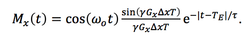
The amplitude of the echo depends on the factor sin(γGxΔxT)/ (γGxΔxT). For a Gx of zero this factor is one and the result is the same as for the spin-echo. If we repeat this pulse sequence with different values of Gx and measure the amplitude of each echo, we can trace out the function sin(γGxΔxT)/ (γGxΔxT), which is the Fourier transform of the spin distribution as a function of position.
4. Frequency Encoding
To do frequency encoding, we add a readout gradient Gx that is on during the echo and lasts a time T, like in Fig. 18.26 of IPMB. In addition, we include a prepulse of opposite polarity and half duration just before the readout, to cancel any extra phase shift accumulated during the echo. (Russ and I discuss this extra lobe of the Gx pulse when analyzing Fig. 18.29c, but we get its sign wrong).
The free induction decay and the phase reversal caused by the π-pulse are the same as in the spin-echo example. Once Gx begins the result differs. The frequency again depends on x. The phase shifts are: (ω-ωo)t because of the distribution of frequencies, -(ω-ωo)TE from the π pulse, -γGxxT/2 caused by the prepulse, and γGxx(t-(TE -T/2)) during readout. The recorded signal simplifies to
The echo during the readout gradient is (you really must fill in the missing steps yourself to benefit from this post)
5. Conclusion
What do we learn from this example? A phase-encoding gradient changes the amplitude of the echo but not its shape. A frequency-encoding gradient, on the other hand, changes the shape but not the amplitude. Both can be written as a modulated Larmor-frequency signal. In the pulse sequences shown above, the Larmor frequency is drawn too low in order to make the figure clearer. In fact, the Larmor frequencies in MRI are many megahertz, and thousands of oscillations occur during the free induction decay and echo.I analyzed both phase encoding and frequency encoding in the x direction and considered each individually, because I wanted to compare and contrast their behavior. In practice, frequency encoding is performed using a Gx gradient in the x direction and phase encoding with a Gy gradient in the y direction, mapping out the two-dimensional Fourier transform of the spin distribution (see IPMB for more).
Until I did this calculation I never completely understood what the shape of the echo looks like during readout. I hope it helps you as much as it helped me. Enjoy!


No comments:
Post a Comment