Friday, July 19, 2024

Happy Birthday, Robert Plonsey!

Wednesday was the 100th anniversary of Robert Plonsey’s birth. He is one of the most highly cited authors in Intermediate Physics for Medicine and Biology.

Plonsey was born on July 17, 1924 in New York City. He served in the navy during the second world war and then obtained his PhD in electrical engineering from Berkeley. In 1957 he joined Case Institute of Technology (now part of Case Western Reserve University) as an Assistant Professor. In 1983 he moved from Case to Duke University, joining their biomedical engineering department.

Plonsey and Barr, Biophys. J.,
45:557–571, 1984.
To honor Plonsey’s birthday, I want to look at one of my favorite papers: “Current Flow Patterns in Two-Dimensional Anisotropic Bisyncytia with Normal and Extreme Conductivities.” He and his Duke collaborator Roger Barr published it forty years ago, in the March, 1984 issue of the Biophysical Journal (Volume 45, Pages 557–571). The abstract is given below.
Cardiac tissue has been shown to function as an electrical syncytium in both intracellular and extracellular (interstitial) domains. Available experimental evidence and qualitative intuition about the complex anatomical structure support the viewpoint that different (average) conductivities are characteristic of the direction along the fiber axis, as compared with the cross-fiber direction, in intracellular as well as extracellular space. This report analyzes two-dimensional anisotropic cardiac tissue and achieves integral equations for finding intracellular and extracellular potentials, longitudinal currents, and membrane currents directly from a given description of the transmembrane voltage. These mathematical results are used as a basis for a numerical model of realistic (though idealized) two-dimensional cardiac tissue. A computer stimulation based on the numerical model was executed for conductivity patterns including nominally normal ventricular muscle conductivities and a pattern having the intra- or extracellular conductivity ratio along x, the reciprocal of that along y. The computed results are based on assuming a simple spatial distribution for [the transmembrane potential], usually a circular isochrone, to isolate the effects on currents and potentials [on] variations in conductivities without confounding propagation differences. The results are in contrast to the many reports that explicitly or implicitly assume isotropic conductivity or equal conductivity ratios along x and y. Specifically, with reciprocal conductivities, most current flows in large loops encompassing several millimeters, but only in the resting (polarized) region of the tissue; further, a given current flow path often includes four or more rather than two transmembrane excursions. The nominally normal results showed local currents predominantly with only two transmembrane passages; however, a substantial part of the current flow patterns in two-dimensional anisotropic bisyncytia may have qualitative as well as quantitative properties entirely different from those of one-dimensional strands.
This article was one of the first to analyze cardiac tissue using the bidomain model. In 1984 (the year before I published my first scientific paper as a young graduate student at Vanderbilt University) the bidomain model was only a few years old. Plonsey and Barr cited Otto Schmitt, Walter Miller, David Geselowitz, and Les Tung as the originators of the bidomain concept. One of Plonsey and Barr’s key insights was the role of anisotropy, and in particular the role of differences of anisotropy in the intracellular and extracellular spaces (sometimes referred to as “unequal anisotropy ratios”), in determining the tissue behavior. In their calculation, they assumed a known transmembrane potential wavefront and calculated the potentials and currents in the intracellular and extracellular spaces.

Plonsey and Barr found that for isotropic tissue, and for tissue with equal anisotropy ratios, the intracellular and extracellular currents were equal and opposite, so the net current (intracellular plus extracellular) was zero. However, for nominal conductivities that have unequal anisotropy ratios they found the net current did not cancel, but instead formed loops that extended well outside the region of the wave front.

Looking back at this paper after several decades, the computational technique seems cumbersome and the plots of the current distributions look primitive. However, Plonsey and Barr were among the first to examine these issues, and when you’re first you can be forgiven if the analysis isn’t as polished as in subsequent reports.

When Plonsey and Barr’s paper was published, my graduate advisor John Wikswo realized the the large current loops they predicted would produce a measurable magnetic field. That story I’ve told before in this blog. Plonsey’s article led directly to Nestor Sepulveda and Wikswo’s paper on the biomagnetic field signature of the bidomain model, indirectly to my adoption of the bidomain model for studying a strand of cardiac tissue, and ultimately to the Sepulveda/Roth/Wikswo analysis of unipolar electrical stimulation of cardiac tissue

Happy birthday, Robert Plonsey. We miss ya!

Friday, July 12, 2024

Taylor Series

The Taylor series is particularly useful for analyzing how functions behave in limiting cases. This is essential when translating a mathematical expression into physical intuition, and I would argue that the ability to do such translations is one of the most important skills an aspiring physicist needs. Below I give a dozen examples from Intermediate Physics for Medicine and Biology, selected to give you practice with Taylor series. In each case, expand the function in the dimensionless variable that I specify. For every example—and this is crucial—interpret the result physically. Think of this blog post as providing a giant homework problem about Taylor series.

Find the Taylor series of:
  1. Eq. 2.26 as a function of bt (this is Problem 26 in Chapter 2). The function is the solution for decay plus input at a constant rate. You will need to look up the Taylor series for an exponential, either in Appendix D or in your favorite math handbook. I suspect you’ll find this example easy.
  2. Eq. 4.69 as a function of ξ (this is Problem 47 in Chapter 4). Again, the Taylor series for an exponential is required, but this function—which arises when analyzing drift and diffusion—is more difficult than the last one. You’ll need to use the first four terms of the Taylor expansion.
  3. The argument of the inverse sine function in the equation for C(r,z) in Problem 34 of Chapter 4, as a function of z/a (assume r is less than a). This expression arises when calculating the concentration during diffusion from a circular disk. Use your Taylor expansion to show that the concentration is uniform on the disk surface (z = 0). This calculation may be difficult, as it involves two different Taylor series. 
  4. Eq. 5.26 as a function of ax. Like the first problem, this one is not difficult and merely requires expanding the exponential. However, there are two equations to analyze, arising from the study of countercurrent transport
  5. Eq. 6.10 as a function of z/c (assume c is less than b). You will need to look up or calculate the Taylor series for the inverse tangent function. This expression indicates the electric field near a rectangular sheet of charge. For z = 0 the electric field is constant, just as it is for an infinite sheet.
  6. Eq. 6.75b as a function of b/a. This equation gives the length constant for a myelinated nerve axon with outer radius b and inner radius a. You will need the Taylor series for ln(1+x). The first term of your expansion should be the same as Eq. 6.75a: the length constant for an unmyelinated nerve with radius a and membrane thickness b.
  7. The third displayed equation of Problem 46 in Chapter 7 as a function of t/tC. This expression is for the strength-duration curve when exciting a neuron. Interestingly, the short-duration behavior is not the same as for the Lapicque strength-duration curve, which is the first displayed equation of Problem 46.
  8. Eq. 9.5 as a function of [M']/[K]. Sometimes it is tricky to even see how to express the function in terms of the required dimensionless variable. In this case, divide both sides of Eq. 9.5, to get [K']/[K] in terms of [M']/[K]. This problem arises from analysis of Donnan equilibrium, when a membrane is permeable to potassium and chloride ions but not to large charged molecules represented by M’.
  9. The expression inside the brackets in Eq. 12.42 as a function of ξ. The first thing to do is to find the Taylor expansion of sinc(ξ), which is equal to sin(ξ)/ξ. This function arises when solving tomography problems using filtered back projection.
  10. Eq. 13.39 as a function of a/z. The problem is a little confusing, because you want the limit of large (not small) z, so that a/z goes to zero. The goal is to show that the intensity falls off as 1/z2 for an ultrasonic wave in the Fraunhoffer zone.
  11. Eq. 14.33 as a function of λkBT/hc. This problem really is to determine how the blackbody radiation function behaves as a function of wavelength λ, for short wavelength (high energy) photons. You are showing that Planck's blackbody function does not suffer from the ultraviolet catastrophe.
  12. Eq. 15.18 as a function of x. (This is Problem 15 in Chapter 15). This function describes how the Compton cross section depends on photon energy. Good luck! (You’ll need it).

Brook Taylor
Who was Taylor? Brook Taylor (1685-1731) was an English mathematician and a fellow of the Royal Society. He was a champion of Newton’s version of the calculus over Leibniz’s, and he disputed with Johann Bernoulli. He published a book on mathematics in 1715 that contained his series.

Friday, July 5, 2024

Depth of Field and the F-Stop

In Chapter 14 of Intermediate Physics for Medicine and Biology, Russ Hobbie and I briefly discuss depth of field: the distance between the nearest and the furthest objects that are in focus in an image captured with a lens. However, we don’t go into much detail. Today, I want to explain depth of field in more—ahem—depth, and explore its relationship to other concepts like the f-stop. Rather than examine these ideas quantitatively using lots of math, I’ll explain them qualitatively using pictures.

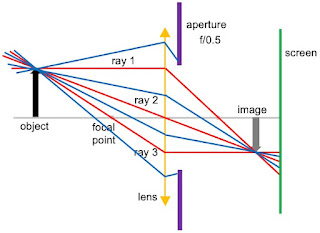
Consider a simple optical system consisting of a converging lens, an aperture, and a screen to detect the image. This configuration looks like what you might find in a camera with the screen being film (oh, how 20th century) or an array of light detectors. Yet, it also could be the eye, with the aperture representing the pupil and the screen being the retina. We’ll consider a generic object positioned to the left of the focal point of the lens. 


To determine where the image is formed, we can draw three light rays. The first leaves the object horizontally and is refracted by the lens so it passes through the focal point on the right. The second passes through the center of the lens and is not refracted. The third passes through the focal point on the left and after it is refracted by the lens it travels horizontally. Where these three rays meet is where the image forms. Ideally, you would put your screen at this location and record a nice crisp image. 


Suppose you are really interested in another object (not shown) to the right of the one in the picture above. Its image would be to the right of the image shown, so that is where we place our screen. In that case, the image of our first object would not be in focus. Instead, it would form a blur where the three rays hit the screen. The questions for today are: how bad is this blurring and what can we do to minimize it?

So far, we haven’t talked about the aperture. All three of our rays drawn in red pass through the aperture. Yet, these aren’t the only three rays coming from the object. There are many more, shown in blue below. Ones that hit the lens near its top or bottom never reach the screen because they are blocked by the aperture. The size of the blurry spot on the screen is specified by a dimensionless number called the f-stop: the ratio of the aperture diameter to the focal length of the lens. It is usually written f/#, where # is the numerical value of the f-stop. In the picture below, the aperture diameter is twice the focal length, so the f-stop is f/0.5.

 
We can reduce the blurriness of the out-of-focus object by partially closing the aperture. In the illustration below, the aperture is narrower and now has a diameter equal to the focal length, so the f-stop is f/1. More rays are blocked from reaching the screen, and the size of the blur is decreased. In other words, our image looks closer to being in focus than it did before. The blurring of an out-of-focus image is reduced. 


It seems like we got something for nothing. Our image is crisper and better just by narrowing the aperture. Why not narrow it further? We can, and the figure below has an f-stop of f/2. The blurring is reduced even more. But we have paid a price. The narrower the aperture, the less light reaches the screen. Your image is dimmer. And this is a bigger effect than you might think from my illustration, because the amount of light goes as the square of the aperture diameter (think in three dimensions). To make up for the lack of light, you could detect the light for a longer time. In a camera, the shutter speed indicates how long the aperture is open and light reaches the screen. Usually as the f-stop is increased (the aperture is narrowed), the shutter speed is changed so the light hits the screen for a longer time. If you are taking a picture of a stationary object, this is not a problem. If the object is moving, you will get a blurry image not because the image is out of focus on the screen, but because the image is moving across the screen. So, there are tradeoffs. If you want a large depth of focus and you don’t mind using a slow shutter speed, use a narrow aperture (a large f-stop). If you want to get a picture of a fast moving object using a fast shutter speed, your image may be too dim unless you use a wide aperture (small f-stop), and you will have to sacrifice depth of field. 

With your eye, there is no shutter speed. The eye is open all the time, and your pupil adjusts its radius to let in the proper amount of light. If you are looking at objects in dim light, your pupil will open up (have a larger radius) and you will have problems with depth-of-focus. In bright light the pupil will narrow down and images will appear crisper. If you are like me and you want to read some fine print but you forgot where you put your reading glasses, the next best thing is to try reading under a bright light.

Most photojournalists use fairly large f-stops, like f/8 or f/16, and a shutter speed of perhaps 5 ms. The human eye has an f-stop between f/2 (dim light) and f/8 (bright light). So, my illustrations above aren’t really typical; the aperture is generally much narrower.

Friday, June 28, 2024

Could Ocean Acidification Deafen Dolphins?

In Chapter 13 of Intermediate Physics for Medicine and Biology, Russ Hobbie and I discuss the attenuation of sound.
Water transmits sound better than air, but its attenuation is an even stronger function of frequency. It also depends on the salt content. At 1000 Hz, sound attenuates in fresh water by about 4 × 10⁻⁴ dB km−1. The attenuation in sea water is about a factor of ten times higher (Lindsay and Beyer 1989). The low attenuation of sound in water (especially at low frequencies) allows aquatic animals to communicate over large distances (Denny 1993).
“Ocean Acidification and the Increasing Transparency of the Ocean to Low-Frequency Sound,” Oceanography, 22: 86–93, 2009 superimposed on the cover of Intermediate Physics for Medicine and Biology.
“Ocean Acidification and the
Increasing Transparency of the Ocean
to Low-Frequency Sound,”
Oceanography, 22: 86–93, 2009.
To explore further into the attenuation of sound in seawater—and especially to examine that mysterious comment “it also depends on the salt content”— I will quote from an article by Peter Brewer and Keith Hester, titled “Ocean Acidification and the Increasing Transparency of the Ocean to Low-Frequency Sound” (Oceanography, Volume 22, Pages 86–93, 2009). The abstract is given below.
As the ocean becomes more acidic, low-frequency (~1–3 kHz and below) sound travels much farther due to changes in the amounts of pH-dependent species such as dissolved borate and carbonate ions, which absorb acoustic waves. The effect is quite large; a decline in pH of only 0.3 causes a 40% decrease in the intrinsic sound absorption properties of surface seawater. Because acoustic properties are measured on a logarithmic scale, and neglecting other losses, sound at frequencies important for marine mammals and for naval and industrial interests will travel some 70% farther with the ocean pH change expected from a doubling of CO2. This change will occur in surface ocean waters by mid century. The military and environmental consequences of these changes have yet to be fully evaluated. The physical basis for this effect is well known: if a sound wave encounters a charged molecule such as a borate ion that can be “squeezed” into a lower-volume state, a resonance can occur so that sound energy is lost, after which the molecule returns to its normal state. Ocean acousticians recognized this pH-sound linkage in the early 1970s, but the connection to global change and environmental science is in its infancy. Changes in pH in the deep sound channel will be large, and very-low-frequency sound originating there can travel far. In practice, it is the frequency range of ~ 300 Hz–10 kHz and the distance range of ~ 200–900 km that are of interest here.
To get additional insight, let us examine the structure of the negatively charged borate ion. It consists a central boron atom surrounded by four hydroxyl (OH) groups in a tetrahedral structure: B(OH)4. Also of interest is boric acid, which is uncharged and has the boron atom attached to three OH groups in a planar structure: B(OH)3. In water, the two are in equilibrium

B(OH)4 + H+ ⇔ B(OH)3 + H2O .

The equilibrium depends on pH and pressure. Brewer and Hester write
Boron exists in seawater in two forms—the B(OH)4 ion and the un-ionized form B(OH)3; their ratio is set by the pH of bulk seawater, and as seawater becomes more acidic, the fraction of the ionized B(OH)4 form decreases. Plainly, the B(OH)4 species is a bigger molecule than B(OH)3 and, because of its charge, also carries with it associated water molecules as a loose assemblage. This weakly associated complex can be temporarily compressed into a lower-volume form by the passage of a sound wave; there is just enough energy in a sound wave to do it. This compression takes work and thus robs the sound wave of some of its energy. Once the wave front has passed by, the B(OH)4 molecules return to their original volumes. Thus, in a more acidic ocean with fewer of the larger borate ions to absorb sound energy, sound waves will travel farther.
As sound waves travel farther, the oceans could become noisier. This behavior has even led one blogger to ask “could ocean acidification deafen dolphins?” 

Researchers at the Woods Hole Oceanographic Institution are skeptical of a dramatic change in sound wave propagation. In an article asking “Will More Acidic Oceans be Noisier?” science reporter Cherie Winner describes modeling studies by Woods Hole scientists such as Tim Duda. Winner explains
Results of the three models varied slightly in their details, but all told the same tale: The maximum increase in noise level due to more acidic seawater was just 2 decibels by the year 2100—a barely perceptible change compared to noise from natural events such as passing storms and big waves.
Duda said the main factor controlling how far sound travels in the seas will be the same in 100 years as it is today: geometry. Most sound waves will hit the ocean bottom and be absorbed by sediments long before they could reach whales thousands of kilometers away.
The three teams published their results in three papers in the September 2010 issue of the Journal of the Acoustical Society of America.
“We did these studies because of the misinformation going around,” said Duda. “Some papers implied, ‘Oh my gosh, the sound absorption will be cut in half, therefore the sound energy will double, and the ocean will be really noisy.’ Well, no, it doesn’t work that way.” 
So I guess we shouldn’t be too concerned about deafening those dolphins, but this entire subject is fascinating and highlights the role of physics for understanding medicine and biology.

Friday, June 21, 2024

Patrick Blackett and Pair Production

Patrick Blackett.
In Chapter 15 of Intermediate Physics for Medicine and Biology, Russ Hobbie and I describe pair production.
A photon… can produce a particle-antiparticle pair: a negative electron and a positron… Since the rest energy (mec2) of an electron or positron is 0.51 MeV, pair production is energetically impossible for photons below 2mec2 = 1.02 MeV…

Pair production always takes place in the Coulomb field of another particle (usually a nucleus) that recoils to conserve momentum.

I often wonder how surprising or unexpected phenomena are discovered. Pair production was first observed by English physicist Patrick Blackett. Here is part of the entry about Blackett in Asimov’s Biographical Encyclopedia of Science & Technology.

Asimov’s Biographical
Encyclopedia of
Science & Technology.
BLACKETT, Patrick Maynard
English physicist
Born: London, November 18, 1897
Died: London, July 13, 1974

Blackett entered a naval school in 1910, at thirteen, to train as a naval officer. The outbreak of World War I came just in time to make use of him and he was at sea throughout the war, taking part in the Battle of Jutland.

With the war over, however, he resigned from the navy and went to Cambridge, where he studied under Ernest Rutherford and obtained his master’s degree in 1923. In 1933 he became professor of physics at the University of London, moving on to Manchester in 1937.

It was Blackett who first turned to the wholesale use of the Wilson cloud chamber [a box containing moist air which produces a visible track when an ion passes through it, condensing the moisture into tiny droplets]…

In 1935 Blackett showed that gamma rays, on passing through lead, sometimes disappear, giving rise to a positron and an electron. This was the first clear-cut case of the conversion of energy into matter. This confirmed the famous E = mc2 equation of Einstein as precisely as did the more numerous examples, earlier observed, of the conversion of matter to energy (and even more dramatically).

During World War II, Blackett worked on the development of radar and the atomic bomb… After the war, however, he was one of those most vociferously concerned with the dangers of nuclear warfare. In 1948 he was awarded the Nobel Prize in physics for his work with and upon the Wilson cloud chamber.

More detail about the discovery of pair production specifically can be found at the Linda Hall Library website.

In 1929, Paul Dirac had predicted the possibility of antimatter, specifically anti-electrons, or positrons, as they would eventually be called. His prediction was purely a result of his relativistic quantum mechanics, and had no experimental basis, so Blackett (with the help of an Italian vsitor, Giuseppe Occhialini), went looking, again with the help of a modified cloud chamber. Blackett suspected that the newly discovered cosmic rays were particles, and not gamma rays (as Robert Millikan at Caltech maintained). Blackett thought that a cosmic particle traveling very fast might have the energy to strike a nucleus and create an electron-positron pair, as Dirac predicted. They installed a magnet around the cloud chamber, to make the particles curve, and rigged the cloud chamber to a Geiger counter, so that the camera was triggered only when the Geiger counter detected an interaction. As a result, their photographs showed interactions nearly every time. They took thousands, and by 1932, 8 of those showed what appeared to be a new particle with the mass of an electron but curving in the direction of a positively charged particle. They had discovered the positron. But while Blackett, a very careful experimenter, checked and double-checked the results, a young American working for Millikan, Carl Anderson, detected positive electrons in his cloud chamber at Caltech in August of 1932, and he published his results first, in 1933. Anderson's discovery was purely fortuitous – he did not even know of Dirac's prediction. But in 1936, Anderson received the Noble Prize in Physics, and Blackett and Occhialini did not, which irritated the British physics community no end, although Blackett never complained or showed any concern. His own Nobel Prize would come in 1948, when he was finally recognized for his break-through work in particle physics.
If you watched last summer’s hit movie Oppenheimer, you might recall a scene where a young Oppenheimer tried to poison his supervisor with a apple injected with cyanide. That supervisor was Patrick Blackett.

The Nobel Prize committee always summarizes a recipient’s contribution in a brief sentence. I’ll end with Blackett’s summary:
"for his development of the Wilson cloud chamber method, and his discoveries therewith in the fields of nuclear physics and cosmic radiation"


The scene from Oppenheimer when Oppie poisons Blackett’s apple.

https://www.youtube.com/watch?v=P8RBHS8zrfk


Patrick Blackett—Draw My Life. From the Operational Research Society.

https://www.youtube.com/watch?v=jg5IQ5Hf2G0

Friday, June 14, 2024

Bernard Leonard Cohen (1924–2012)

The Nuclear Energy Option: An Alternative for the 90s. by Bernard Cohen, superimposed on Intermediate Physics for Medicine and Biology.
The Nuclear Energy Option: An Alternative for the 90s.
by Bernard Cohen.
Today is the one hundredth anniversary of the birth of American nuclear physicist Bernard Cohen. In Intermediate Physics for Medicine and Biology, Russ Hobbie and I discuss Cohen mainly in the context of his work on the risk of low levels of ionizing radiation and his opposition to the linear no threshold model. Today, I will examine another aspect of his work: his advocacy for nuclear power. In particular, I will review his 1990 book The Nuclear Energy Option: An Alternative for the 90s.

Why read a 35-year old book about a rapidly changing technology like energy? I admit, the book is in some ways obsolete. Cohen insists on using rems as his unit of radiation effective dose, rather than the more modern Sievert (Sv). He discusses the problem of greenhouse gases and global warming, although in a rather hypothetical way as just one of the many problems with burning fossil fuels. He was optimistic about the future of nuclear energy, but we know now that in the decades following the book’s publication nuclear power in the United States did not do well (the average age of our nuclear power plants is over 40 years). Yet other features of the book have withstood the test of time. As our world now faces the dire consequences of climate change, the option of nuclear energy is an urgent consideration. Should we reconsider nuclear power as an alternative to coal/oil/natural gas? I suspect Cohen would say yes.

In Chapter 4 of The Nuclear Energy Option Cohen writes
We have seen that we will need more power plants in the near future, and that fueling them with coal, oil, or gas leads to many serious health, environmental, economic, and political problems. From the technological points of view, the obvious way to avoid these problems is to use nuclear fuels. They cause no greenhouse effect, no acid rain, no pollution of the air with sulfur dioxide, nitrogen oxides, or other dangerous chemicals, no oil spills, no strain on our economy from excessive imports, no dependence on unreliable foreign sources, no risk of military ventures. Nuclear power almost completely avoids all the problems associated with fossil fuels. It does have other impacts on our health and environment, which we will discuss in later chapters, but you will see that they are relatively minor.
He then compares the safety and economics of nuclear energy with other options, including solar and coal-powered plants for generating electricity. Some of the conclusions are surprising. For instance, you might think that energy conservation is always good (who roots for waste?). But Cohen writes
Another energy conservation strategy is to seal buildings more tightly to reduce the escape of heat, but this traps unhealthy materials like radon inside. Tightening buildings to reduce air leakage in accordance with government recommendations would give the average American an LLE [loss of life expectancy] of 20 days due to increased radon exposure, making conservation by far the most dangerous energy strategy from the standpoint of radiation exposure!
His Chapter 8 on Understanding Risk is a classic. He begins
One of the worst stumbling blocks in gaining widespread public acceptance of nuclear power is that the great majority of people do not understand and quantify the risks we face. Most of us think and act as though life is largely free of risk. We view taking risks as foolhardy, irrational, and assiduously to be avoided….

Unfortunately, life is not like that. Everything we do involves risk.

He then makes a catalog of risks, in which he converts risk to the average expected loss of life expectancy for each case. This LLE is really just a measure of probability. For instance, if getting a certain disease shortens your life by ten years, but there is only one chance out of a hundred of contracting that disease, it would correspond to an LLE of 0.1 years, or 36 days. In his catalog, the riskiest activity is living in poverty, which has an LLE of 3500 days (almost ten years). Smoking cigarettes results in an LLE of 2300 days. Being 30 pounds overweight is 900 days. Reducing the speed limit on our highways from 65 to 55 miles per hour would reduce traffic accidents and give us an extra 40 days. At the bottom of his list is living near a nuclear reactor, with a risk of only 0.4 days (less than ten hours). He makes a compelling case that nuclear power is extraordinarily safe.

Cohen summarizes these risks in a classic figure, shown below.

Figure 1 from Chapter 8 of The Nuclear Energy Option, superimposed on Intermediate Physics for Medicine and Biology.
Figure 1 from Chapter 8 of The Nuclear Energy Option.

Our poor risk perception causes us (and our government) to spend money foolishly. He translates societies efforts to reduce risk into the cost in dollars to save one life.

The $2.5 billion we spend to save a single life in making nuclear power safer could save many thousands of lives if spent on radon programs, cancer screening, or transportation safety. This means that many thousands of people are dying unnecessarily every year because we are spending this money in the wrong way.
He concludes
The failure of the American public to understand and quantify risk must rate as one of the most serious and tragic problems for our nation.
I agree.

Cohen believes that Americans have a warped view of the risk of nuclear energy.

The public has become irrational over fear of radiation. Its understanding of radiation dangers has virtually lost all contact with the actual dangers as understood by scientists.
Apparently conspiracy theories are a problem we face not only today but also decades ago, when the scientific establishment was accused of hiding the “truth” about radiation risks. Cohen counters
To believe that such highly reputable scientists conspired to practice deceit seems absurd, if for no other reason than that it would be easy to prove that they had done so and the consequences to their scientific careers would be devastating. All of them had such reputations that they could easily obtain a variety of excellent and well-paying academic positions independent of government or industry financing, so they were to vulnerable to economic pressures.

But above all, they are human beings who have chosen careers in a field dedicated to protection of the health of their fellow human beings; in fact, many of them are M.D.’s who have foregone financially lucrative careers in medical practice to become research scientists. To believe that nearly all of these scientists were somehow involved in a sinister plot to deceive the public indeed challenges the imagination.
To me, these words sound as if Cohen were talking now about vaccine hesitancy or climate change denial, rather than opposition to nuclear energy. 

What do I think? I would love to have solar and wind supply all our energy needs. But until they can, I vote for increasing our use of nuclear energy over continuing to burn fossil fuels (especially coal). Global warming is already bad and getting worse. It is a dire threat to us all and to our future generations. We should not rule out nuclear energy as one way to address climate change.

Happy birthday, Bernard Cohen! I think if you had lived to be 100 years old, you would have found so many topics to write about today. How we need your rational approach to risk assessment. 

 Firing Line with William F. Buckley Jr.: The Crisis of Nuclear Energy.

https://www.youtube.com/watch?v=ipOrGaXn-r4&list=RDCMUC9lqW3pQDcUuugXLIpzcUdA&start_radio=1&rv=ipOrGaXn-r4&t=52

Friday, June 7, 2024

The Magnetocardiogram

I recently published a review in the American Institute of Physics journal Biophysics Reviews about the magnetocardiogram (Volume 5, Article 021305, 2024).

The magnetic field produced by the heart’s electrical activity is called the magnetocardiogram (MCG). The first twenty years of MCG research established most of the concepts, instrumentation, and computational algorithms in the field. Additional insights into fundamental mechanisms of biomagnetism were gained by studying isolated hearts or even isolated pieces of cardiac tissue. Much effort has gone into calculating the MCG using computer models, including solving the inverse problem of deducing the bioelectric sources from biomagnetic measurements. Recently, most magnetocardiographic research has focused on clinical applications, driven in part by new technologies to measure weak biomagnetic fields.

This graphical abstract sums the article up. 


Let me highlight one paragraph of the review, about some of my own work on the magnetic field produced by action potential propagation in a slab of cardiac tissue.

The bidomain model led to two views of how an action potential wave front propagating through cardiac muscle produces a magnetic field.58 The first view (Fig. 7a) is the traditional one. It shows a depolarization wave front and its associated impressed current propagating to the left (in the x direction) through a slab of tissue. The extracellular current returns through the superfusing saline bath above and below the slab. This geometry generates a magnetic field in the negative y direction, like that for the nerve fiber shown in Fig. 5. This mechanism for producing the magnetic field does not require anisotropy. The second view (Fig. 7b) removes the superfusing bath. If the tissue were isotropic (or anisotropic with equal anisotropy ratios) the intracellular currents would exactly cancel the equal and opposite interstitial currents, producing no net current and no magnetic field. If, however, the tissue has unequal anisotropy ratios and the wave front is propagating at an angle to the fiber axis, the intracellular current will be rotated toward the fiber axis more than the interstitial current, forming a net current flowing in the y direction, perpendicular to the direction of propagation.59–63 This line of current generates an associated magnetic field. These two views provide different physical pictures of how the magnetic field is produced in cardiac tissue. In one case, the intracellular current forms current dipoles in the direction parallel to propagation, and in the other it forms lines of current in the direction perpendicular to propagation. Holzer et al. recorded the magnetic field created by a wave front in cardiac muscle with no superfusing bath present, and observed a magnetic field distribution consistent with Fig. 7b.64 In general, both mechanisms for producing the magnetic field operate simultaneously.


FIG. 7. Two mechanisms for how cardiac tissue produces a magnetic field.

This figure is a modified (and colorized) version of an illustration that appeared in our paper in the Journal of Applied Physics.

58. R. A. Murdick and B. J. Roth, “A comparative model of two mechanisms from which a magnetic field arises in the heart,” J. Appl. Phys. 95, 5116–5122 (2004). 

59. B. J. Roth and M. C. Woods, “The magnetic field associated with a plane wave front propa-gating through cardiac tissue,” IEEE Trans. Biomed. Eng. 46, 1288–1292 (1999). 

60. C. R. H. Barbosa, “Simulation of a plane wavefront propagating in cardiac tissue using a cellular automata model,” Phys. Med. Biol. 48, 4151–4164 (2003). 

61. R. Weber dos Santos, F. Dickstein, and D. Marchesin, “Transversal versus longitudinal current propagation on cardiac tissue and its relation to MCG,” Biomed. Tech. 47, 249–252 (2002). 

62. R. Weber dos Santos, O. Kosch, U. Steinhoff, S. Bauer, L. Trahms, and H. Koch, “MCG to ECG source differences: Measurements and a two-dimensional computer model study,” J. Electrocardiol. 37, 123–127 (2004). 

63. R. Weber dos Santos and H. Koch, “Interpreting biomagnetic fields of planar wave fronts in cardiac muscle,” Biophys. J. 88, 3731–3733 (2005). 

64. J. R. Holzer, L. E. Fong, V. Y. Sidorov, J. P. Wikswo, and F. Baudenbacher, “High resolution magnetic images of planar wave fronts reveal bidomain properties of cardiac tissue,” Biophys. J. 87, 4326–4332 (2004).

The first author is Ryan Murdick, an Oakland University graduate student who analyzed the mechanism of magnetic field production in the heart for his masters degree. He then went to Michigan State University for a PhD in physics and now works for Renaissance Scientific in Boulder, Colorado. I’ve always thought Ryan’s thesis topic about the two mechanisms is underappreciated, and I’m glad I had the opportunity to reintroduce it to the biomagnetism community in my review. It’s hard to believe it has been twenty years since we published that paper. It seems like yesterday.

Tuesday, June 4, 2024

Yesterday’s Attack on Dr. Anthony Fauci During his Testimony at the Congressional Select Subcommittee on the Coronavirus Pandemic Angers Me

Yesterday’s attack on Dr. Anthony Fauci during his testimony at the Congressional Select Subcommittee on the Coronavirus Pandemic angers me. I like Dr. Fauci and I like other vaccine scientists such as Peter Hotez and writers such as David Quammen who tell their tales. But, it isn’t really about them. What upsets me most is the attack on science itself; on the idea that evidence matters; on the idea that science is the way to determine the truth; on the idea that truth is important. I’m a scientist; it’s an attack on me. We must call it out for what it is: a war on science. #StandWithScience

Friday, May 31, 2024

Can the Microwave Auditory Effect Be ‘Weaponized’

Can the Microwave Auditory
Effect be Weaponized?”
I was recently reading Ken Foster, David Garrett, and Marvin Ziskin’s paper “Can the Microwave Auditory Effect Be Weaponized?” (Frontiers in Public Health, Volume 9, 2021). It analyzed if microwave weapons could be used to “attack” diplomats and thereby cause the Havana syndrome. While I am interested in the Havana syndrome (I discussed it in my book Are Electromagnetic Fields Making Me Ill?), today I merely want to better understand Foster et al.’s proposed mechanism by which an electromagnetic wave can induce an acoustic wave in tissue.

As is my wont, I will present this mechanism as a homework problem at a level you might find in Intermediate Physics for Medicine and Biology. I’ll assign the problem to Chapter 13 about Sound and Ultrasound, although it draws from several chapters.

Forster et al. represent the wave as decaying exponentially as it enters the tissue, with a skin depth λ. To keep things simple and to focus of the mechanism rather than the details, I’ll assume the energy in the electromagnetic wave is absorbed uniformly in a thin layer of thickness λ, ignoring the exponential behavior.

Section 13.4
Problem 17 ½. Assume an electromagnetic wave of intensity I0 (W/m2) with area A (m2) and duration τ (s) is incident on tissue. Furthermore, assume all its energy is absorbed in a depth λ (m).

(a) Derive an expression for the energy E (J) dissipated in the tissue.

(b) Derive an expression for the tissue’s increase in temperature ΔT (°C), E = C ΔT, where C (J/°C) is the heat capacity. Then express C in terms of the specific heat capacity c (J/°C kg), the density ρ (kg/m3), and the volume where the energy was deposited V (m3). (For a discussion of the heat capacity, see Sec. 3.11).

(c) Derive an expression for the fractional increase in volume, ΔV/V, caused by the increase in temperature, ΔV/V = αΔT, where α (1/°C) is the tissue’s coefficient of thermal expansion.

(d) Derive an expression for the change in pressure, ΔP (Pa), caused by this fractional change in volume, ΔP = B ΔV/V, where B (Pa) is the tissue’s bulk modulus. (For a discussion of the bulk modulus, see Sec. 1.14).

(e) You expression in part d should contain a factor Bα/. Show that this factor is dimensionless. It is called the Grüneisen parameter.

(f) Assume α = 0.0003 1/°C, B = 2 × 10⁹ Pa, c = 4200 J/kg °C, and ρ = 1000 kg/m3. Evaluate the Grüneisen parameter. Calculate the change in pressure ΔP if the intensity is 10 W/m2, the skin depth is 1 mm, and the duration is 1 μs.

I won’t solve the entire problem for you, but the answer for part d is

                            ΔPI0 (τ/λ) [/] .

I should stress that this calculation is approximate. I ignored the exponential falloff. Some of the incident energy could be reflected rather than absorbed. It is unclear if I should use the linear coefficient of thermal expansion or the volume coefficient. The tissue may be heterogeneous. You can probably identify other approximations I’ve made. 

Interestingly, the pressure induced in the tissue varies inversely with the skin depth, which is not what I intuitively expected. As the skin depth gets smaller, the energy is dumped into a smaller volume, which means the temperature increase within this smaller volume is larger. The pressure increase is proportional to the temperature increase, so a thinner skin depth means a larger pressure.

You might be thinking: wait a minute. Heat diffuses. Do we know if the heat would diffuse away before it could change the pressure? The diffusion constant of heat (the thermal diffusivity) D for tissue is about 10-7 m2/s. From Chapter 4 in IPMB, the time to diffuse a distance λ is λ2/D. For λ = 1 mm, this diffusion time is 10 s. For pulses much shorter than this, we can ignore thermal diffusion. 

Perhaps you’re wondering how big the temperature rise is? For the parameters given, it’s really small: ΔT  = 2 × 10–9 °C. This means the fractional change in volume is around 10–12. It’s not a big effect.

The Grüneisen parameter is a dimensionless number. I’m used to thinking of such numbers as being the ratio of two quantities with the same units. For instance, the Reynolds number is the ratio of an inertial force to a viscous force, and the Péclet number is the ratio of transport by drift to transport by diffusion. I’m having trouble interpreting the Grüneisen parameter in this way. Perhaps it has something to do with the ratio of thermal energy to elastic energy, but the details are not obvious, at least not to me.

What does this all have to do with the Havana syndrome? Not much, I suspect. First, we don’t know if the Havana syndrome is caused by microwaves. As far as I know, no one has ever observed microwaves associated with one of these “attacks” (perhaps the government has but they keep the information classified). This means we don’t know what intensity, frequency (and thus, skin depth), and pulse duration to assume. We also don’t know what pressure would be required to explain the “victim’s” symptoms. 

In part f of the problem, I used for the intensity the upper limit allowed for a cell phone, the skin depth corresponding approximately to a microwave frequency of about ten gigahertz, and a pulse duration of one microsecond. The resulting pressure of 0.0014 Pa is much weaker than is used during medical ultrasound imaging, which is known to be safe. The acoustic pressure would have to increase dramatically to pose a hazard, which implies very large microwave intensities.

Are Electromagnetic Fields Making Me Ill? superimposed on the cover of Intermediate Physics for Medicine and Biology.
Are Electromagnetic Fields
Making Me Ill?

That such a large intensity electromagnetic wave could be present without being noticeable seems farfetched to me. Perhaps very low pressures could have harmful effects, but I doubt it. I think I’ll stick with my conclusion from Are Electromagnetic Fields Making Me Ill?

Microwave weapons and the Havana Syndrome: I am skeptical about microwave weapons, but so little evidence exists that I want to throw up my hands in despair. My guess: the cause is psychogenic. But if anyone detects microwaves during an attack, I will reconsider.

Friday, May 24, 2024

Magnetoelectrics For Biomedical Applications

“Magnetoelectrics for Biomedical Applications: 130 years Later, Bridging Materials, Energy, and Life” superimposed on Intermediate Physics for Medicine and Biology.
Magnetoelectrics for
Biomedical Applications:
130 Years Later, Bridging
Materials, Energy, and Life
I’m always looking for new ways physics can be applied to medicine and biology. Recently, I read the article “Magnetoelectrics for Biomedical Applications: 130 Years Later, Bridging Materials, Energy, and Life” by Pedro Martins and his colleagues (Nano Energy, in press).

The “130 years” in the title refers to the year 1894 when Pierre Curie conjectured that in some materials there could be a coupling between their magnetic and electric properties. While there are some single-phase magnetoelectric materials, most modern ones are composites: piezoelectric and magnetostrictive phases are coupled through mechanical strain. In this way, an applied magnetic field can produce an electric field, and vice versa.

Martins et al. outline many possible applications of magnetoelectric materials to medicine. I will highlight three.

  1. Chapter 7 of Intermediate Physics for Medicine and Biology mentions deep brain stimulators to treat Parkinson’s disease. Normally deep brain stimulation requires implanting a pacemaker-like device connected by wires inserted into the brain. A magnetoelectric stimulator could be small and wireless, using power delivered by a time-dependent magnetic field. The magnetic field would induce an electric field in the magnetoelectric material, and this electric field could act like an electrode, activating a neuron
  2. Chapter 8 of IPMB discusses ways to measure the tiny magnetic field produced by the heart: The magnetocardiogram. The traditional way to record the field is to use a superconducting quantum interference device (SQUID) magnetometer, which must be kept at cryogenic temperatures. Martins et al. describe how a weak magnetic field would produce a measurable voltage using a room-temperature magnetoelectric sensor.
  3. Magnetoelectric materials could be used for drug delivery. Martins et al. describe an amazing magnetoelectrical “nanorobot” that could be made to swim using a slowly rotating magnetic field. After the nanorobot reached its target, it could be made to release a cancer-fighting drug to the tissue by applying a rapidly changing magnetic field that produces a local electric field strong enough to cause electroporation in the target cell membrane, allowing delivery of the drug.

What I have supplied is just a sample of the many various applications of magnetoelectric materials. Martin’s et al. describe many more, and also provide a careful analysis to the limitations of these techniques. 

The third example related to drug delivery surprised me. Electroporation? Really? That requires a huge electric field. In Chapter 9 of IPMB, Russ Hobbie and I say that for electroporation the electric field in the membrane should be about 108 volts per meter. Later in that chapter, we analyze an example of a spherical cell in an electric field. To get a 108 V/m electric field in the membrane, the electric field applied to the cell as a whole should be on the order of 108 V/m times the thickness of the membrane (about 10–8 m) divided by the radius of the cell (about 10–5 m), or 105 V/m. The material used for drug delivery had a magnetoelectrical coefficient of about 100 volts per centimeter per oersted, which means 104 V/(m Oe). The oersted is really a unit of the magnetic field intensity H rather than of the magnetic field B. In most biological materials, the magnetic permeability is about that of a vacuum, so 1 Oe corresponds to 1 gauss, or 10–4 tesla. Therefore, the magnetoelectrical coefficient is 108 (V/m)/T. Martins et al. say that a magnetic field of about 1000 Oe (0.1 T) was used in these experiments. So, the electric field produced by the material was on the order of 107 V/m. The electric field that cells adjacent to the magnetoelectrical particle experience should be about this strength. We found earlier that electroporation requires an electric field applied to the cell of around 105 V/m. That means we should have about a factor of 100 more electric field strength than is needed. It should work, even if the neuron is a little bit distant from the device. Wow!

I’ll close with my favorite paragraph of the article, found near the end and summarizing the field.

The historical trajectory of ME [magnetoelectric] materials, spanning from Pierre Curie's suggestion in 1894 to recent anticancer activities in 2023, has been characterized by significant challenges and breakthroughs that have shaped their biomedical feasibility. Initially, limited understanding of the ME phenomenon and the absence of suitable materials posed critical obstacles. However, over the decades, intensive research efforts led to the discovery and synthesis of ME compounds, including novel composite structures and multiferroic materials with enhanced magnetoelectric coupling. These advancements, coupled with refinements in material synthesis and characterization techniques, propelled ME materials into the realm of biomedical applications. Additionally, piezoelectric polymers have been incorporated into ME composites, enhancing processing, biocompatibility, integration, and flexibility while maintaining or even improving the ME properties of the composite materials. In the 21st century, the exploration of ME materials for biomedical purposes gained momentum, particularly in anticancer activities. Breakthroughs in targeted drug delivery, magnetic hyperthermia therapy, and real-time cancer cell imaging showcased the therapeutic potential of ME materials. Despite these advancements, challenges such as ensuring biocompatibility, stability in physiological environments, and scalability for clinical translation persist. Ongoing research aims to optimize ME material properties for specific cancer types, enhance targeting efficiency, and address potential cytotoxicity concerns, with the ultimate goal of harnessing the full potential of ME materials to revolutionize cancer treatment and diagnosis.